Introduction
Surgical robots demand unparalleled precision in motion control to perform minimally invasive procedures with sub-millimeter accuracy. The printed circuit board (PCB) serves as the central nervous system, integrating sensors, actuators, and control algorithms into a compact form factor. Optimizing surgical robot PCB motion control involves balancing high-speed signal integrity, low-latency feedback, and thermal stability under continuous operation. Precision PCB design becomes critical as even minor layout flaws can amplify errors in robotic arm movements. This article explores engineering strategies for enhancing accuracy through targeted PCB techniques. Electric engineers must prioritize these elements to meet the rigorous demands of surgical robotics feedback systems.
Why Precision Motion Control Matters in Surgical Robotics
Precision motion control in surgical robots ensures that end-effectors follow trajectories with minimal deviation, directly impacting patient outcomes. Robotic arms handle delicate tissues, where latencies exceeding microseconds can lead to tremors or overshoots. PCB layout for robotic arms influences the overall system response time, as signal paths determine propagation delays. In feedback-intensive applications, poor design introduces noise that corrupts position data from encoders or force sensors. Engineers face challenges from electromagnetic interference (EMI) in operating rooms, compounded by high-density component placement. Adhering to standards like IPC-6012E for rigid board qualification helps validate designs against performance criteria.

Surgical robotics feedback systems rely on closed-loop control, where PCBs process real-time data from inertial measurement units and resolvers. Any impedance mismatch or crosstalk degrades loop stability, potentially causing instability in PID controllers. Power supply noise couples into analog lines, affecting amplifier performance for servo drives. Thermal expansion in multilayer boards can shift trace alignments over time, necessitating materials with low coefficients of thermal expansion. These factors underscore the need for holistic precision PCB design from schematic capture through fabrication.
Core Technical Principles of Surgical Robot PCB Motion Control
Surgical robot PCB motion control hinges on maintaining signal integrity for high-frequency pulses driving stepper or brushless motors. Differential signaling pairs carry encoder quadrature signals, requiring controlled 100-ohm impedance to prevent reflections. Clock lines for field-programmable gate arrays (FPGAs) handling trajectory planning must exhibit sub-nanosecond skew across layers. Ground planes shield sensitive traces, while via stitching minimizes inductance in return paths. Parasitic effects like skin effect at gigahertz frequencies demand wider traces and smoother copper plating. These principles form the foundation for reliable operation in dynamic environments.
Feedback mechanisms in surgical robotics feedback systems amplify the importance of analog-to-digital converter (ADC) placement near sensors. Low-noise power rails, decoupled with ceramic capacitors tuned to loop bandwidths, suppress ripple that could alias into position readings. Isolation barriers, such as optocouplers or transformers, prevent common-mode noise from propagating between motor drives and control processors. Thermal vias under high-power field-effect transistors (FETs) dissipate heat, preserving gain in operational amplifiers. Engineers must model these interactions using field solvers to predict behaviors before prototyping.
Latency in control loops arises from propagation delays, serialization overhead, and processing bottlenecks on the PCB. Minimizing latency in surgical robot PCBs requires short, direct routing for critical nets like pulse-width modulation (PWM) outputs. Stubs on high-speed buses introduce ringing, mitigated by length-matching within 0.5 millimeters. Power distribution networks (PDNs) with low equivalent series inductance (ESL) ensure stable voltages for microcontrollers executing real-time operating systems. Vias in series add capacitance, so blind or buried vias reduce stub lengths in dense designs.
Precision PCB Design Techniques for Enhanced Accuracy
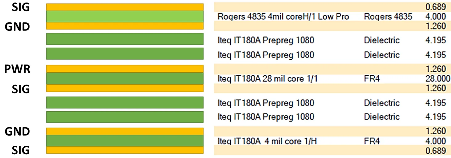
Precision PCB design starts with stackup optimization, using symmetric builds to control warpage under thermal cycling. Core dielectrics with dielectric constant (Dk) stability, such as FR-4 variants with low loss tangents, support gigabit transceivers for vision feedback integration. Eight-layer or higher stacks segregate power, ground, and signal planes, reducing crosstalk by 20 decibels or more. Prepreg selection influences via reliability, adhering to IPC-2221B guidelines for land and trace spacing. Copper weight balancing prevents bow and twist, critical for connector mating in robotic joints.
Component selection emphasizes low-jitter clocks and high-common-mode rejection ratio (CMRR) amplifiers for surgical robotics feedback systems. Surface-mount resistors with 0.1% tolerance set gain in current-sense circuits for torque control. Ball grid array (BGA) packages for processors demand fanout strategies with microvias to escape signals without lengthening paths. Decoupling strategies place 0.1 microfarad capacitors within 1 millimeter of power pins, supplemented by higher-value electrolytics for bulk storage. These techniques collectively enhance motion control precision.
Thermal management in precision PCB design addresses heat from power stages driving robotic actuators. Copper pours under FETs, combined with embedded heat pipes, channel heat to chassis sinks. Via farms plated with heavy copper conduct flux away from hotspots, maintaining junction temperatures below 125 degrees Celsius. Conformal coatings protect against humidity-induced failures in sterile environments. Finite element analysis verifies these approaches, ensuring coefficient of thermal expansion (CTE) matching between PCB and components.
PCB Layout Best Practices for Robotic Arms
PCB layout for robotic arms prioritizes partitioning to isolate noisy digital sections from precision analog circuits. Dedicated ground planes for each domain, connected via single-point stitching at 0.5 wavelengths, prevent ground bounce. High-current motor traces routed on inner layers with parallel returns minimize loop areas, reducing radiated emissions. Length-tuned serpentine routes equalize delays for multi-axis synchronization. Guard traces around resolvers shield against capacitive coupling.
Minimizing latency in surgical robot PCBs involves prioritizing critical paths in autorouters or manual routing. FPGA I/O banks assigned to adjacent layers reduce via count, cutting delay by picoseconds per transition. Serialization interfaces like LVDS preserve eye opening through back-drilling unused vias. PDN impedance targets below 1 milliohm up to 100 megahertz, verified with time-domain reflectometry. Compliance with J-STD-001 ensures soldering processes do not introduce defects affecting high-speed performance.
Routing density challenges in compact surgical robot designs necessitate HDI structures with laser-drilled microvias. Stacked microvias fill with conductive epoxy for reliability under vibration. Escape patterns for fine-pitch QFNs use dog-bone transitions to enlarge lands without stubs. These practices enhance surgical robot PCB motion control reliability.
Challenges and Troubleshooting in Precision Designs
Common challenges include EMI pickup in unshielded cables interfacing with PCBs, addressed by filtering ferrites on I/O lines. Crosstalk between parallel traces exceeds budgets when spacing falls below 3 times the dielectric height. Troubleshooting involves TDR scans to identify discontinuities, followed by rerouting. Thermal runaway in densely packed power sections triggers watchdog resets, resolved by active cooling integration. Vibration from arm movements loosens connectors, mitigated by locking hardware and strain relief.
Feedback loop oscillations from phase delays require Bode plot analysis during bench testing. Adjusting compensator networks on the PCB stabilizes gains. IPC-A-600K acceptability criteria guide visual inspections for defects like measling that compromise dielectric strength. Systematic debugging preserves the precision essential for surgical applications.
Conclusion
Optimizing surgical robot PCB design for precision motion control demands a multifaceted approach encompassing signal integrity, layout strategies, and thermal control. Key practices like controlled impedance routing, partitioned grounds, and low-latency paths directly enhance accuracy in robotic arms. Surgical robotics feedback systems benefit from noise-immune analog sections and robust PDNs. By applying these engineering principles, electric engineers can minimize latency in surgical robot PCBs, ensuring reliable performance. Standards integration and rigorous verification solidify designs against real-world stresses. Future advancements will further refine these techniques for next-generation systems.
FAQs
Q1: What is surgical robot PCB motion control, and why is it essential?
A1: Surgical robot PCB motion control refers to the PCB's role in processing commands for actuators and sensors to achieve precise movements. It integrates high-speed interfaces and feedback loops critical for sub-millimeter accuracy during procedures. Poor control leads to positioning errors, compromising safety. Engineers optimize it through impedance control and low-noise layouts, aligning with reliability standards for medical applications.
Q2: How does precision PCB design improve surgical robotics feedback systems?
A2: Precision PCB design enhances surgical robotics feedback systems by minimizing noise in sensor signals and ensuring fast ADC sampling. Techniques like ground plane isolation and decoupling reduce interference, stabilizing closed-loop performance. Thermal stability prevents drift in gain stages. This results in accurate position and force data, vital for tremor-free operation. Layout partitioning separates domains effectively.
Q3: What are best practices for PCB layout for robotic arms?
A3: PCB layout for robotic arms prioritizes short, matched-length traces for synchronization and wide power paths for low inductance. Partition noisy motor drives from control logic using planes. Microvias enable dense routing without stubs. Verify with simulations to cut crosstalk. These steps ensure vibration-resistant, high-reliability designs for dynamic motions.
Q4: How can engineers minimize latency in surgical robot PCBs?
A4: Minimizing latency in surgical robot PCBs involves direct routing of critical nets, reducing via counts, and optimizing PDN impedance. Length-matching skew-sensitive signals and using high-speed dielectrics speed propagation. Decoupling at the source suppresses jitter. Testing with oscilloscopes confirms sub-microsecond responses, essential for real-time control.
References
IPC-6012E — Qualification and Performance Specification for Rigid Printed Boards. IPC, 2017
IPC-2221B — Generic Standard on Printed Board Design. IPC, 2012
J-STD-001H — Requirements for Soldered Electrical and Electronic Assemblies. IPC, 2020
IPC-A-600K — Acceptability of Printed Boards. IPC, 2020


