Introduction
Creating printed circuit boards at home opens up exciting possibilities for electronics projects, allowing hobbyists to prototype ideas without relying on professional services. Accurate PCB drilling forms the foundation of a functional board, as it determines where components mount and how traces connect. Even small deviations in hole position or size can cause assembly failures or signal integrity issues. This guide focuses on simple, effective techniques tailored for DIY setups, drawing from established manufacturing principles. By following these methods, electronic hobbyists can achieve professional-level results using basic tools. Whether building a custom sensor or a simple controller, precise drilling elevates your PCB layout from sketch to reality.
Why Accurate PCB Drilling Matters for DIY PCB Projects
In electronics projects, the PCB serves as the backbone that integrates components into a compact, reliable system. Inaccurate drilling leads to problems like misaligned pads, broken vias, or components that do not seat properly, wasting time and materials. For hobbyists working on DIY PCBs, precision ensures the board matches the intended PCB layout, supporting everything from through-hole components to edge connectors. Industry standards like IPC-6012E emphasize tight tolerances for hole location and diameter to maintain electrical performance and mechanical stability. Poor drilling can also introduce burrs or cracks in the laminate, compromising long-term durability. Mastering accurate PCB drilling techniques thus boosts project success rates and builds confidence in home fabrication.
Understanding the Basics of PCB Drilling
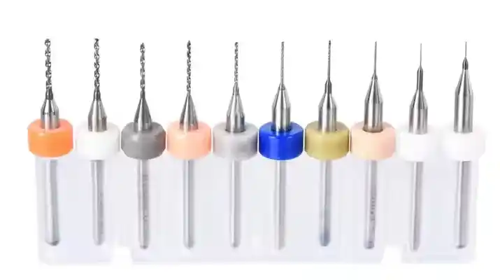
PCB drilling involves creating precisely located holes in the board substrate to accommodate component leads, vias, and mounting hardware. Most hobbyist boards use FR-4 epoxy glass laminate, which requires sharp, specialized tools to avoid delamination or cracking. Drill bits for PCBs differ from wood or metal types; they feature polished flutes and specific geometries for clean entry and exit. Hole sizes typically range from 0.2 mm for fine-pitch vias to 1.5 mm for standard resistors, demanding careful selection based on your PCB layout. The process generates heat and debris, so controlling speed and feed rates prevents bit wear or board damage. Grasping these fundamentals sets the stage for reliable drilling techniques in home workshops.
Essential Tools for Accurate Home PCB Drilling
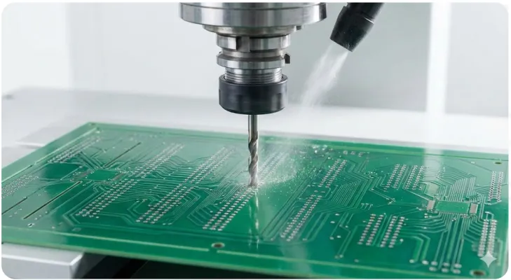
A stable drill press forms the core of any home setup for accurate PCB drilling, providing consistent perpendicular entry unlike handheld drills. Invest in a micro drill press with variable speed control, ideally from 1000 to 50000 RPM depending on bit size. Carbide end mills or spiral bits in sizes matching your design work best, as they resist the abrasive nature of fiberglass. Additional tools include a sturdy vise or fixture to secure the board, a microscope or magnifying loupe for alignment checks, and a vacuum system to clear chips. Backing material like phenolic or sacrificial wood prevents breakout on the exit side. With these, hobbyists can replicate factory precision in electronics projects.
Preparing Your PCB for Drilling
Start by printing your PCB layout at 1:1 scale on transparent film or paper, ensuring toner transfer or photoresist exposure aligns perfectly with the blank board. Double-check artwork against the physical copper layers using a lightbox for overlay verification. Clean the board surface with isopropyl alcohol to remove oils that could shift the template. Apply the drill template securely with tape, punching pilot marks at each hole center using a fine awl. Secure the board flat on the drill bed with clamps, avoiding any flex that warps the substrate. This preparation minimizes errors, aligning home drilling with professional PCB manufacturing workflows.
Step-by-Step Drilling Techniques for Precision
Begin drilling with the largest holes first to establish reference points, then progress to smaller ones to maintain stability. Set spindle speed inversely proportional to bit diameter: higher RPM for tiny vias, lower for larger mounting holes. Use peck drilling, plunging 0.1 to 0.2 mm per pass and retracting to clear chips, which prevents bit binding and heat buildup. Maintain light, even pressure without forcing the bit, letting the tool do the work. After each hole, inspect for straightness and size using calipers, adjusting as needed. These drilling techniques ensure holes meet positional accuracy suitable for DIY PCB assembly.
Controlling Drill Speed and Feed for Optimal Results
Proper speed selection avoids common pitfalls like bit breakage or oversized holes in PCB materials. For a 0.5 mm bit in FR-4, aim for 20000 to 30000 RPM with shallow feeds to generate minimal heat. Monitor for signs of overheating, such as blueing on the bit or smoking laminate, and pause to cool if necessary. Feed rate depends on automation level; manual setups require steady hand control to mimic machine consistency. Consistent parameters across your PCB layout promote uniform hole quality. Adhering to these practices aligns with IPC-A-600K criteria for acceptable hole walls and plating readiness.
Securing the Board to Prevent Movement
Board fixturing ranks as one of the simplest yet most effective ways to achieve accurate PCB drilling at home. Use a custom jig with registration pins matching fiducials on your layout, or improvise with double-sided tape on a flat aluminum plate. Avoid over-tightening clamps that bow the board, as warpage exceeds tolerances defined in manufacturing specs. Test fixturing by nudging the setup; zero movement confirms readiness. For multi-layer stacks, drill panelized boards together before singulation. Solid hold-downs transform variable hand-drilling into repeatable precision for electronics projects.
Deburring and Finishing Drilled Holes
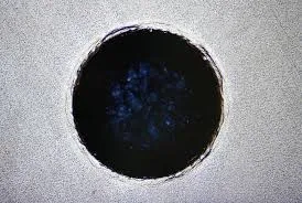
Post-drilling cleanup removes copper burrs and fiberglass whiskers that snag components during assembly. Use a countersink bit or fine file for entry-side chamfering, followed by nylon abrasive brushing for walls. Immerse in a deburring solution or scrub with Scotch-Brite pads under running water. Inspect under magnification for residue, as contaminants affect solderability. This step ensures clean interfaces matching IPC standards for surface finish. Finished holes ready your DIY PCB for etching or plating experiments.
Troubleshooting Common Drilling Issues
Misaligned holes often stem from template slippage or drill wander; verify alignment with a pin gauge before full runs. Oversized holes result from dull bits or excessive speed; replace bits after 50-100 holes and recalibrate RPM. Chipping at exits indicates lacking backing; always use sacrificial material underneath. If holes are elliptical, check spindle runout or board flatness. Systematic checks resolve these, keeping your PCB layout intact. Patience in troubleshooting yields boards fit for complex electronics projects.
Advanced Tips for Professional-Grade Home Drilling
Incorporate a digital readout on your drill press Z-axis for depth-controlled blind vias in multi-layer DIY PCBs. Experiment with lubricant sprays designed for composites to extend bit life and improve finish. For high-density layouts, use CNC routers if budget allows, programming G-code from your design files. Maintain a log of speeds, feeds, and outcomes to refine processes over projects. Reference J-STD-001 for assembly implications of drill quality. These enhancements bridge hobbyist and factory divides.
Conclusion
Accurate PCB drilling at home empowers electronic hobbyists to realize ambitious DIY PCB designs with reliability. From tool selection and preparation to execution and finishing, each technique builds toward flawless results. Standards like IPC-6012E and IPC-A-600K guide these practices, ensuring compatibility with professional workflows. Avoid common pitfalls through methodical approaches, and your electronics projects will perform as intended. Experiment iteratively, document successes, and watch your skills grow. With these simple methods, home fabrication becomes a powerful extension of your creative toolkit.
FAQs
Q1: What are the best drill bits for accurate PCB drilling in DIY projects?
A1: Carbide spiral or straight flute bits sized to your PCB layout work best for FR-4 boards. Select diameters matching component leads plus 0.1 mm clearance for plating. Store bits in a protective case to prevent damage. Use a bit gauge for verification before starting. This ensures clean cuts without excessive wear during electronics projects.
Q2: How can I ensure straight holes in home PCB drilling techniques?
A2: Secure the board rigidly in a vise or fixture to eliminate flex. Employ a drill press with a right-angle collet for perpendicular entry. Peck drill to clear debris and reduce wander. Check alignment with a pin after every few holes. These steps deliver the precision needed for reliable DIY PCB assembly.
Q3: Why do holes chip during accurate PCB drilling, and how to fix it?
A3: Chipping occurs from high speeds or no backing material on FR-4. Lower RPM for larger bits and place sacrificial wood underneath. Use sharp carbide tools and light pressure. Inspect laminate quality beforehand. Proper setup prevents defects, aligning with standards for hole integrity in electronics projects.
Q4: What speed settings suit different drilling techniques for PCBs?
A4: Small bits under 0.5 mm need 30000+ RPM, while 1 mm bits use 15000 RPM. Adjust feed shallowly to avoid heat. Test on scrap first. Consistent speeds promote uniform results across your PCB layout. Monitor bit condition to maintain accuracy in home setups.
References
IPC-6012E - Qualification and Performance Specification for Rigid Printed Boards. IPC, 2017
IPC-A-600K - Acceptability of Printed Boards. IPC, 2020
J-STD-001H - Requirements for Soldered Electrical and Electronic Assemblies. IPC, 2018


