Introduction
Assembling metal-backed PCBs opens up exciting possibilities for electronic hobbyists tackling projects with high heat output, such as LED lighting arrays or audio amplifiers. These boards feature a metal core that enhances thermal performance compared to standard FR4 substrates, making them ideal for prototypes where overheating could ruin components. This PCB assembly guide walks beginners through the entire process, from preparation to final testing, with a focus on practical tips for both surface-mount technology (SMT) and through-hole assembly. You’ll learn soldering metal PCB techniques tailored to the unique challenges of metal-backed designs, ensuring reliable results without advanced equipment. By following these steps, hobbyists can achieve professional-quality assemblies at home. Let’s dive into the essentials to get your project powered up safely and efficiently.
What Are Metal-Backed PCBs and Why Do They Matter for Hobbyists?
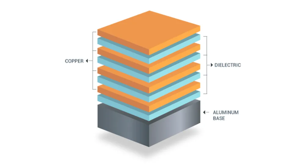
Metal-backed PCBs, also known as metal core printed circuit boards (MCPCBs), consist of a thick metal base layer, typically aluminum or copper, bonded to a thin dielectric layer and topped with copper traces. This construction allows superior heat dissipation by channeling thermal energy directly away from power components to the metal backing, which acts as a natural heat sink. For electronic hobbyists, these boards matter because many DIY projects involve high-current devices like power LEDs, motor drivers, or RF modules that generate significant heat on standard boards. Without proper thermal management, components can fail prematurely or cause board delamination. Metal-backed designs solve this by maintaining lower operating temperatures, extending component life and improving reliability. In hobbyist applications, they enable compact builds that perform like commercial products, all while keeping costs reasonable for prototyping.
The relevance extends to experimentation; hobbyists often push boundaries with overdriven LEDs or amplifiers, where metal-backed PCBs prevent hotspots that warp or degrade FR4 boards. Their rigidity also reduces flexing during handling, a common issue in benchtop assembly. Understanding this structure helps anticipate assembly differences, such as increased thermal mass during soldering. Hobbyists benefit from these boards in maker spaces or garage labs, where space heaters or 3D-printed enclosures double as heat sinks post-assembly. Overall, incorporating metal-backed PCB assembly into your toolkit elevates project durability and opens doors to advanced thermal designs.
Key Technical Principles of Metal-Backed PCB Assembly
The core principle behind metal-backed PCBs lies in their thermal conductivity path: heat from traces flows through the thin dielectric into the metal base far faster than in fiberglass boards. Aluminum PCBs, common for cost-effectiveness, offer about 1-2 W/mK conductivity in the dielectric, still vastly superior to FR4’s 0.3 W/mK. This setup demands adjusted assembly processes because the metal absorbs solder heat rapidly, prolonging melt times and risking cold joints if not managed. During SMT assembly, reflow profiles must account for this mass to avoid underheating pads or overheating components. Through-hole assembly faces similar hurdles, as leads passing near the core pull heat away from joints.
Another mechanism is mechanical stability; the metal layer minimizes warpage from thermal cycling, adhering to principles in IPC-6012 for rigid board performance. These structural advantages are fundamental to high-performance PCB assembly key design considerations, where isolated vias and weight-balanced fixturing ensure reliability. Thermal expansion mismatch is low, reducing stress cracks and guiding safe handling practices for complex, heat-intensive designs.
Step-by-Step Best Practices for Metal-Backed PCB Assembly
1. Prepare Your Workspace and Gather Tools
Start with a clean, well-lit ESD-safe workspace to protect sensitive components from static discharge, using a mat and wrist strap for hobbyist setups. Essential tools include a temperature-controlled soldering iron (set to 350-400°C for lead-free solder), flux pen, no-clean solder wire (0.5-1mm diameter), tweezers, isopropyl alcohol for cleaning, and a magnifying glass or microscope. For SMT, add low-melt solder paste, a stencil if available, or a syringe for manual application, plus a hot air station or toaster oven for reflow. Secure the heavy metal-backed PCB with clamps or double-sided tape on a heat-resistant surface to counter its weight. Inspect the board for defects like burrs or contamination, wiping with alcohol. Preheat the oven or board to 100-150°C if possible, easing the heat sink effect.
2. Inspect Components and PCB
Before metal-backed PCB assembly, verify component datasheets for thermal ratings matching the board’s capabilities. Check the PCB for plating integrity on pads and vias, ensuring no oxidation from storage. Use a multimeter to confirm no shorts between traces and the metal back, a common oversight. Sort components by size, prioritizing large power devices for first placement to leverage the core’s cooling. Bake hygroscopic parts per J-STD-020 guidelines if exposed to humidity, preventing reflow voids. Document your setup with photos for troubleshooting later.
3. Perform SMT Assembly
Apply solder paste precisely to pads using a stencil or fine applicator, focusing on power pads where heat dissipation matters most. Place components with tweezers, aligning fine-pitch parts under magnification; the metal core’s flatness aids stability. For reflow, use a profile ramping to 220-260°C peak for lead-free, holding longer than FR4 due to thermal mass, typically 60-90 seconds above liquidus. Hot air works for hobbyists: start low flow at 300°C, increasing as needed while monitoring with a thermocouple. Avoid direct flame; flux activation prevents oxidation on the metal-exposed edges. After cooling, clean residues gently to reveal shiny joints.
4. Handle Through-Hole Assembly
Insert through-hole leads into plated holes, bending them slightly to hold position against the board’s rigidity. Apply flux to joints, then solder from the component side, feeding wire while heating pads adequately to overcome core cooling. Use a larger tip for power pins, dwelling 3-5 seconds per joint to form full fillets without bridging. Trim excess leads post-solder with flush cutters, avoiding nicks that stress the plating. For mixed assembly, do SMT first to prevent disturbing placed parts. This through-hole assembly sequence ensures mechanical strength complements the thermal advantages.
5. Soldering Metal PCB: Specialized Tips
Soldering metal PCB requires adapting to rapid heat sinking: always preheat the board underside with a heat gun or plate to 120°C, reducing iron dwell time and preventing delamination. Choose flux with high activation for aluminum interfaces, applying generously to pads. For hand soldering, increase iron temp by 20-30°C over standard, but never exceed component limits. In wave soldering setups rare for hobbyists, ensure conveyor speed accounts for mass. Post-solder, inspect for voids using IPC J-STD-001 criteria, reheating if needed with fresh solder. These techniques yield robust joints resilient to thermal cycling.
6. Clean, Inspect, and Test
Clean flux residues with isopropyl alcohol and a soft brush, avoiding abrasives on the metal back. Visual inspection under light checks for cold joints, bridges, or tombstoning, common in uneven heating. Use IPC-A-610 class 2 or 3 criteria for acceptability, measuring continuity and shorts with a multimeter. Functional test powers the board gradually, monitoring temperatures with a non-contact thermometer. Attach a heat sink if designed, using thermal paste for interface. Bake test at 85°C for stress screening if time allows.
Common Troubleshooting for Metal-Backed PCB Assembly
Cold solder joints top the list, fixed by preheating and flux; insufficient heat leaves dull, cracked appearances. Tombstoning in SMT arises from rapid core cooling one side, mitigated by symmetric paste volume. Through-hole voids occur from trapped air, resolved by flux and slow insertion. Warpage is minimal but check flatness post-reflow. Overheating components signal poor profiles, so log temperatures. Sequential assembly prevents rework damage.
Conclusion
Mastering metal-backed PCB assembly empowers hobbyists to build durable, high-performance electronics with confidence. From workspace prep to final testing, each step addresses the thermal uniqueness of these boards, ensuring reliable SMT and through-hole results. Key takeaways include preheating for soldering metal PCB challenges, standard-compliant inspections, and thorough testing. Experiment safely, iterating on profiles for your projects. With practice, these techniques become second nature, unlocking creative thermal designs.
FAQs
Q1: What makes soldering metal PCB different from standard FR4?
A1: Soldering metal PCB demands higher temperatures or preheating due to the core’s heat absorption, prolonging melt times. Use ample flux and temperature-controlled irons to form proper joints without damaging components. This PCB assembly guide emphasizes these adjustments for beginners in metal-backed PCB assembly.
Q2: Can beginners do SMT assembly on metal-backed boards at home?
A2: Yes, with solder paste, tweezers, and a hot air station or reflow oven. Preheat the board to counter thermal mass, following ramp-soak-peak profiles. Practice on scrap first for precise placement in this SMT assembly process.
Q3: How do I avoid common issues in through-hole assembly on metal-backed PCBs?
A3: Secure components firmly, apply flux liberally, and dwell longer on joints to overcome cooling. Trim leads carefully post-solder to prevent shorts. This through-hole assembly approach ensures strong mechanical bonds.
Q4: What tools are essential for a metal-backed PCB assembly guide?
A4: Prioritize ESD protection, temp-controlled soldering gear, flux, magnifier, and multimeter. Optional hot air for SMT elevates hobbyist setups without factory costs.
References
IPC J-STD-001G — Requirements for Soldered Electrical and Electronic Assemblies. IPC, 2017
IPC-A-610H — Acceptability of Electronic Assemblies. IPC, 2019
IPC-6012E — Qualification and Performance Specification for Rigid Printed Boards. IPC, 2017


