Introduction
Flexible printed circuit boards, or flex PCBs, enable compact designs in space-constrained applications by allowing bending and folding without compromising electrical performance. The choice of copper thickness plays a pivotal role in balancing electrical conductivity, mechanical flexibility, and reliability. Among various options, 1 oz copper stands out as a standard weight in flexible PCB 1 oz copper configurations, equivalent to approximately 35 microns of foil thickness. This thickness provides sufficient current-carrying capacity for many designs while maintaining manufacturability. However, engineers must weigh its benefits against challenges like limited bend radii in dynamic environments. Understanding these trade-offs is essential for effective flex PCB design and material selection in flexible PCBs.
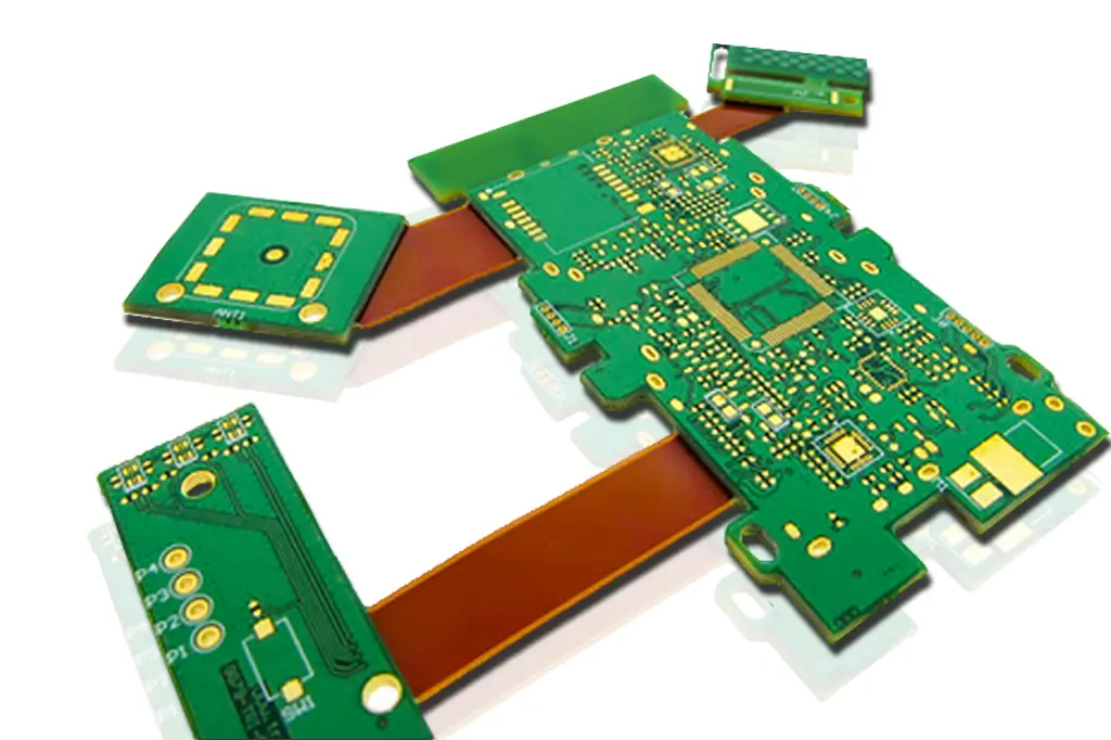
As electrical engineers optimize layouts for wearables, medical devices, and automotive systems, the role of 1 oz copper becomes critical. It supports reliable signal integrity and power distribution in applications of flexible PCBs where rigidity is undesirable. This article explores the technical principles, advantages, limitations, and best practices for using 1 oz copper in flex circuits. By adhering to established guidelines, designers can mitigate risks and enhance performance.
What Is 1 oz Copper and Why It Matters in Flexible PCBs
1 oz copper refers to copper foil weighing 1 ounce per square foot, translating to a nominal thickness of 35 microns after processing. In flexible PCBs, this copper forms the conductive traces and planes, bonded to substrates like polyimide using adhesive or adhesiveless lamination. Rolled annealed (RA) copper foil is preferred for flex applications due to its grain structure, which enhances ductility over electrodeposited types. The weight directly influences trace width requirements for current handling and overall board stiffness.
In flex PCB design, copper thickness affects the minimum bending radius, fatigue life, and impedance control. Thicker foils like 1 oz provide better thermal dissipation and mechanical strength during assembly, making them suitable for static flex regions. However, in dynamic areas with repeated bending, thinner foils reduce stress concentrations. Material selection for flexible PCBs must consider copper weight alongside dielectric properties. Polyimide offers high thermal stability and low moisture absorption, complementing 1 oz copper for harsh environments. Engineers evaluate these factors to meet signal integrity and reliability goals without over-specifying thickness. Industry standards such as IPC-6013E outline qualification requirements for these constructions, ensuring consistency across classes 1 through 3.
Technical Principles of 1 oz Copper in Flex Circuits
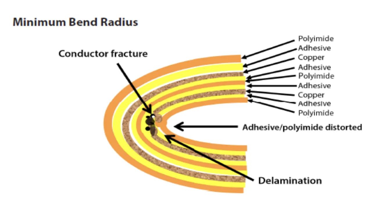
The mechanical behavior of flexible PCB 1 oz copper stems from copper's ductility and the substrate's elasticity. During bending, outer traces elongate while inner ones compress, generating strain proportional to copper thickness and bend radius. IPC-2223E provides design guidelines for calculating allowable bend radii based on layer count, copper weight, and flex cycles. For a typical double-sided flex with 1 oz copper on polyimide, static bends require radii several times the total stack-up thickness to avoid cracking.
Electrically, 1 oz copper delivers adequate cross-sectional area for currents up to several amps per trace, minimizing voltage drops in power nets. Its resistance is lower than thinner foils, supporting high-speed signals with controlled impedance. Thermal expansion mismatch between copper and polyimide demands careful coverlay application to prevent delamination under cycling.
Fatigue mechanisms accelerate with thicker copper, as grain boundaries crack under cyclic strain. RA foil mitigates this through elongated grains aligned with bend direction. Engineers model these using finite element analysis to predict lifespan, ensuring compliance with application demands.
Benefits of 1 oz Copper in Flexible PCBs
One primary advantage of flexible PCB 1 oz copper is cost-effectiveness, as it leverages standard manufacturing processes without specialized thin-foil handling. This weight balances electrical performance and economy, ideal for moderate power applications of flexible PCBs like sensors and displays. It supports wider traces for heat dissipation, reducing hotspot risks in compact assemblies.
Manufacturability improves with 1 oz copper, enabling finer line widths down to 0.1 mm in high-volume production while maintaining etch uniformity. Assembly yields benefit from robust traces less prone to tearing during handling or soldering. In rigid-flex hybrids, it transitions smoothly to rigid sections without reinforcement.
Reliability in static and semi-dynamic uses shines, with proven endurance in consumer electronics. Its thickness aids in via plating integrity per IPC-6013E criteria, enhancing interlayer connections.
Challenges and Limitations in Flex PCB Design with 1 oz Copper
Despite benefits, the bending radius for 1 oz copper poses significant challenges in tight-space designs. Thicker foil increases minimum bend radius requirements, often 6 to 10 times the flex area thickness for static applications, limiting form factors. Dynamic flexing exacerbates fatigue, as copper work-hardens and cracks after thousands of cycles.
Material selection becomes complex, requiring thinner dielectrics to compensate, which may compromise voltage standoff. Etching 1 oz copper demands precise control to avoid undercuts, raising defect risks in fine-pitch traces. Thermal management suffers in high-density layouts, as heat spreads less efficiently than in heavier coppers.
Solder joint reliability under flex stress is another concern, with thicker traces amplifying peel forces. Engineers must incorporate strain relief features like teardrops and annular rings.

Best Practices for Flex PCB Design with 1 oz Copper
Start with stack-up optimization, placing 1 oz copper on outer layers for power and inner for signals to minimize bend stress. Adhere to IPC-2223E for bend area zoning, avoiding vias and components within flex zones. Simulate bend radii early, targeting at least 10 times thickness for production margins.
Material selection in flexible PCBs favors adhesiveless laminates with polyimide for seamless integration. Use coverlays thicker than copper to distribute strain evenly. Panelize designs with balanced copper distribution to prevent warpage.
For assembly, specify low-stress soldering profiles and polyimide stiffeners at terminations. Prototype testing validates dynamic life, iterating on trace routing like curved paths parallel to bends.
- Minimum Bend Radius (Static): 6-10x flex thickness
- Trace Routing in Bend Area: Parallel to bend axis, no acute angles
- Coverlay Opening: 0.2 mm larger than pad for relief
- Stiffener Placement: At rigid-flex transitions
Applications of Flexible PCBs with 1 oz Copper
In consumer electronics, flexible PCB 1 oz copper powers foldable displays and hinge interconnects, enduring installation bends. Medical devices leverage its reliability for endoscopes and wearables, where biocompatibility and compactness matter. Automotive sensors use it for engine harnesses, tolerating vibration and temperature swings.
Aerospace benefits from lightweight interconnects in avionics, meeting stringent qualification. Industrial robotics employs flex circuits for joint motion, balancing durability and space savings.
Conclusion
1 oz copper remains a versatile choice in flexible PCB 1 oz copper designs, offering strong electrical properties and manufacturability for diverse applications. While challenges like bending radius limitations require careful flex PCB design, best practices rooted in standards mitigate risks. Engineers achieve optimal performance through informed material selection and simulation. As demands for compact electronics grow, mastering these elements ensures reliable, innovative solutions.
FAQs
Q1: What is the typical minimum bending radius for 1 oz copper in flexible PCBs?
A1: The bending radius 1 oz copper in flex PCB design depends on stack-up and application type. For static bends in double-layer polyimide flex, guidelines suggest 6 to 10 times the total thickness to prevent trace cracking. Dynamic uses demand larger radii, often 20 times or more. Always verify with IPC-2223E calculations and prototype testing for reliability.
Q2: Why choose 1 oz copper for material selection in flexible PCBs?
A2: 1 oz copper strikes a balance in material selection for flexible PCBs between conductivity, cost, and strength. It handles moderate currents effectively while supporting standard etching processes. Thinner foils suit extreme flex, but 1 oz excels in semi-dynamic applications like wearables, providing thermal margins without excess stiffness.
Q3: What are common applications of flexible PCBs using 1 oz copper?
A3: Applications of flexible PCBs with 1 oz copper include foldable devices, medical implants, and automotive sensors. These leverage its durability for static-to-moderate bends in compact spaces. It supports high-reliability needs in harsh environments, from consumer gadgets to industrial controls.
Q4: How does 1 oz copper impact flex PCB design challenges?
A4: In flex PCB design, 1 oz copper increases minimum bend radius needs compared to 0.5 oz, challenging tight layouts. It raises fatigue risks in dynamic areas but enhances power delivery. Mitigate with zoned routing, RA foil, and stiffeners for balanced performance.
References
IPC-6013E — Qualification and Performance Specification for Flexible Printed Boards. IPC, 2021
IPC-2223E — Sectional Design Standard for Flexible/Rigid-Flex Printed Boards. IPC, 2020


