Introduction
Semi-flex PCBs represent a practical hybrid solution in modern electronics, blending rigid structural integrity with targeted flexibility to fit compact designs. These boards typically feature a primarily rigid substrate with designated areas thinned or modified for controlled bending, enabling installation in tight spaces without full rigid-flex complexity. Engineers often turn to semi-flex PCB materials FR4 as the foundation due to its proven reliability and affordability, while exploring alternatives for enhanced performance. This guide delves into semi-flex PCB material properties, comparisons, selection criteria, and cost factors, drawing from factory manufacturing perspectives to aid informed decisions. Understanding these elements ensures optimal performance in applications like medical devices and avionics.
What Are Semi-Flex PCBs and Why Do They Matter?
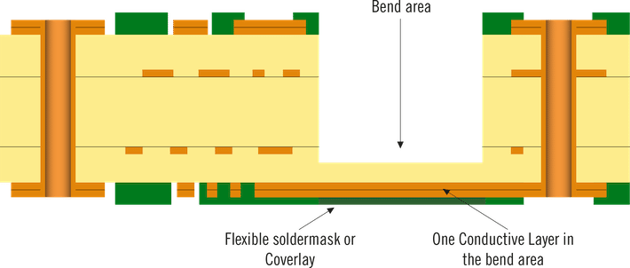
Semi-flex PCBs combine rigid and semi-rigid sections within a single board, where flexible zones are created by thinning the substrate or integrating specialized layers. Unlike fully rigid boards, they allow limited bending during assembly or operation, reducing the need for connectors and cables that introduce failure points. Factory production involves precise depth-controlled milling or lamination to form these zones, maintaining overall planarity for component mounting. This design matters in industries demanding space efficiency, such as wearables and sensors, where traditional rigid PCBs fail to conform to curved enclosures.
The relevance stems from balancing mechanical durability with adaptability, minimizing signal loss in folded configurations. Semi-flex constructions support higher layer counts in rigid areas while limiting flex sections to preserve bend radius integrity. Manufacturers emphasize symmetry in stack-ups to counteract thermal expansion differences, preventing warpage during soldering. As electronics miniaturize, semi-flex options bridge the gap between cost-prohibitive full-flex boards and inflexible rigid ones.
Core Materials in Semi-Flex PCBs: FR4 and Alternatives
FR4 remains the cornerstone of semi-flex PCB materials FR4 due to its fiberglass-reinforced epoxy resin composition, offering robust mechanical support in rigid sections. Thinning FR4 to 0.1-0.2 mm in flex zones creates bendable areas through controlled depth routing, a cost-effective method for low-cycle applications. Polyimide serves as a key alternative for true flex sections, providing superior ductility and heat resistance when laminated with FR4 outer layers. Hybrids combine FR4 rigid cores with polyimide cores exposed via laser ablation, enabling multi-layer builds up to 16 layers total.
Adhesives and prepregs bond these materials, with low-flow types ensuring minimal resin bleed during lamination. Copper foils, often annealed for flex areas, maintain conductivity under strain. Factory processes prioritize material compatibility to avoid delamination from CTE mismatches between FR4 and polyimide.
Semi-Flex PCB Material Properties
Semi-flex PCB material properties center on mechanical flexibility, thermal stability, and electrical performance tailored to application demands. FR4 exhibits a glass transition temperature around standard levels, suitable for most reflow processes, with low dielectric loss for signal integrity. Its rigidity prevents vibration-induced failures in non-flex zones, though thinned areas limit bend cycles to avoid cracking. Polyimide offers higher thermal endurance and elasticity, ideal for repeated flexing, but requires careful handling to mitigate higher moisture absorption.
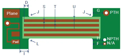
Electrical properties include dielectric constants that influence impedance control, with FR4 providing stable values for high-frequency signals. Mechanical attributes like bend radius depend on layer thickness, typically requiring traces perpendicular to bend lines for stress distribution. Factory testing verifies properties through thermal cycling and flex endurance, aligning with qualification specs.
Semi-Flex PCB Material Comparison
- FR4 (Thinned): Flexibility—Limited (low cycles); Thermal—Standard Tg; Cost—Baseline; Typical use—Rigid cores with occasional bends.
- Polyimide: Flexibility—High (many cycles); Thermal—High Tg; Cost—2-5x higher than FR4; Typical use—Flex sections under high mechanical stress.
- FR4 + Polyimide Hybrid: Flexibility—Moderate; Thermal—Balanced; Cost—1.5-3x higher than FR4; Typical use—Multi-layer hybrids combining rigid and flex needs.
FR4 excels in cost and ease of processing for semi-flex PCB material comparison, dominating rigid portions with excellent punch strength. Polyimide outperforms in dynamic environments, resisting fatigue better than thinned FR4, which risks delamination under repeated stress. Hybrids leverage FR4's affordability with polyimide's ductility, though CTE differences demand symmetric stack-ups to minimize warp.
Electrical comparisons show polyimide's lower dissipation factor suiting RF applications, while FR4 suffices for digital signals. Manufacturing yield favors FR4-based designs due to standard tooling.
Semi-Flex PCB Material Selection Guide
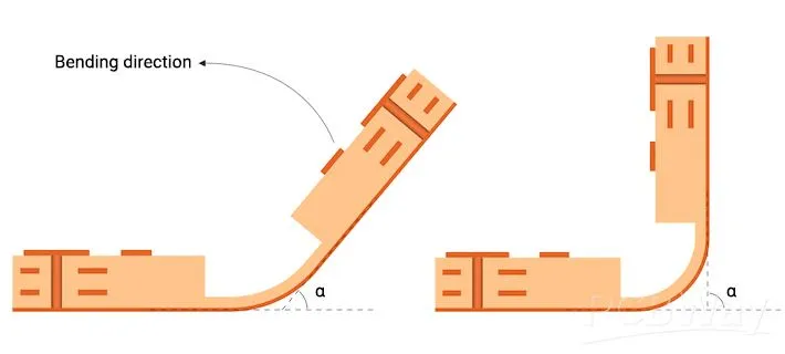
Selecting semi-flex PCB materials begins with defining bend frequency and radius, favoring thinned FR4 for static folds and polyimide for dynamic use. Evaluate operating temperature; FR4 handles typical assembly, but high-heat scenarios require polyimide hybrids. Consider layer count and impedance needs, ensuring flex cores stay under six layers for viability.
Factory insights stress symmetry and material balancing per IPC-2223 design guidelines to prevent twisting. Prototype testing for warpage and continuity guides final choices. For space-constrained designs, prioritize hybrids despite added steps.
Component density influences rigid area materials, with FR4 supporting dense SMT. Signal speed dictates low-loss options. Always align with performance specs from IPC-6013 for qualification.
Factors Influencing Semi-Flex PCB Material Cost
Semi-flex PCB material cost hinges on base substrate volume, with FR4 offering the lowest per square inch due to abundant supply and simple processing. Polyimide integration raises expenses through specialized lamination and laser milling, often doubling costs for flex-heavy designs. Layer complexity amplifies this, as multi-layer hybrids demand precise registration and adhesives.
Volume orders reduce per-unit impact, but small runs incur setup premiums for depth-controlled routing. Thinned FR4 semi-flex minimizes cost over full polyimide by limiting flex material. Factory optimization, like combining rigid and flex lines, further controls expenses.
Best Practices for Manufacturing and Design
Adhere to IPC-2223 for trace routing, using curved paths and teardrops to distribute bend stress. Position vias away from flex zones, at least 0.5 mm from transitions, to avoid cracking. Employ staggered traces in multi-layers for uniform thinning.
Lamination requires low-flow prepregs to bond FR4 and polyimide without voids. Post-milling inspections check for resin smear per IPC-A-600 acceptability. Thermal profiling ensures Tg compatibility during reflow.
Conclusion
Semi-flex PCB materials FR4 provide a versatile, economical base, extendable via polyimides for demanding flexibility. Key properties like CTE and bend endurance guide comparisons and selections, balancing performance with cost. Factory-driven practices, rooted in standards, ensure reliability. Engineers benefit from this hybrid approach in compact, reliable designs.
FAQs
Q1: What are the main semi-flex PCB material properties to consider for electric engineers?
A1: Semi-flex PCB material properties include mechanical bend radius, thermal glass transition temperature, and dielectric constant for impedance stability. FR4 offers rigidity and low cost, while polyimide provides higher flex cycles and heat resistance. Engineers must evaluate CTE mismatch in hybrids to prevent warpage, aligning with IPC-6013 qualification. Factory testing verifies endurance under thermal cycling.
Q2: How does semi-flex PCB material comparison favor FR4 over alternatives?
A2: In semi-flex PCB material comparison, FR4 stands out for affordability and process compatibility in rigid sections, with thinning enabling basic flex. Polyimide excels in cycles but increases cost; hybrids balance both. FR4 suits low-flex applications like sensors. Selection weighs application stress against budget and reliability targets.
Q3: What is a semi-flex PCB material selection guide for cost-sensitive projects?
A3: Prioritize FR4 for baseline cost, reserving polyimide for essential flex zones. Assess bend needs, layer symmetry, and production volume to optimize. Thinned FR4 hybrids cut expenses relative to full-flex builds. Consult IPC-2223 for design rules and viability under intended mechanical stresses.
Q4: How do semi-flex PCB materials FR4 impact overall manufacturing costs?
A4: FR4 lowers costs through standard tooling and high yield, ideal for prototypes and volume production. Alternatives like polyimide add lamination and laser processing premiums. Optimize by minimizing flex area size, maintaining symmetric stack-ups, and leveraging factory scaling to reduce per-unit semi-flex PCB material cost.
References
IPC-2223 — Sectional Design Standard for Flexible/Rigid-Flexible Printed Boards. IPC
IPC-6013 — Qualification and Performance Specification for Flexible/Rigid-Flexible Printed Boards. IPC
IPC-A-600 — Acceptability of Printed Boards. IPC


