Introduction
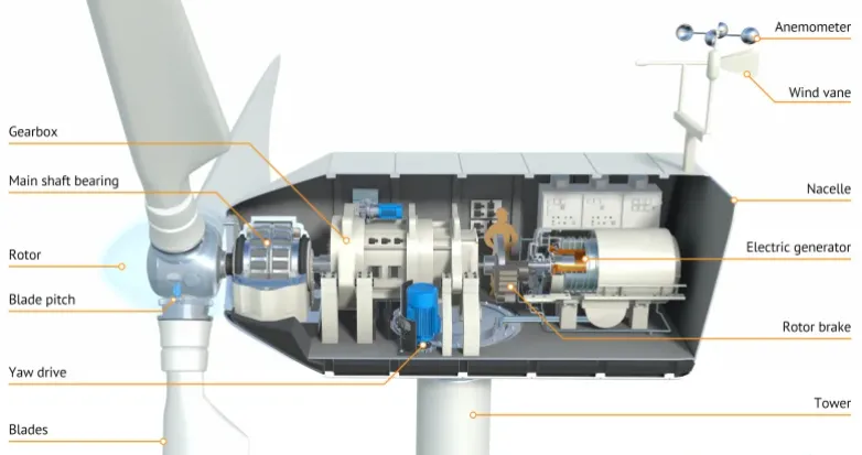
Wind turbine control systems rely on printed circuit boards (PCBs) to manage critical functions like pitch control, yaw adjustment, and generator monitoring. These PCBs operate in nacelles exposed to extreme conditions including high winds, temperature fluctuations, humidity, and vibrations. Offshore installations face additional threats from salt-laden air and corrosive marine environments. Effective wind turbine PCB design guidelines ensure long-term reliability, minimizing downtime and maintenance costs in remote locations. PCB environmental protection strategies become essential to safeguard electronics against these stressors. This guide provides electric engineers with structured insights into designing robust control PCBs for such demanding applications.
Why Wind Turbine Control PCBs Require Specialized Design
Control PCBs in wind turbines handle real-time data from sensors and actuators, demanding uninterrupted performance over 20 years or more. Harsh environments accelerate failure modes like delamination, cracking, and electrical shorts due to moisture ingress and thermal cycling. Onshore sites deal with dust, temperature swings from minus 40 degrees Celsius to plus 60 degrees Celsius, and mechanical shocks from gusts. Offshore turbines encounter saltwater spray, relative humidity up to 100 percent, and constant vibration from rotating components. These factors necessitate PCB designs that exceed standard commercial requirements, focusing on high-reliability features. Engineers must prioritize wind turbine PCB design guidelines that address both electrical performance and mechanical endurance.
Key Challenges in Harsh Environments
Corrosion poses a primary threat to PCB corrosion resistance, as salt aerosols penetrate unprotected surfaces, leading to dendritic growth between conductors. Thermal expansion mismatches between materials cause warpage and solder joint fatigue during rapid temperature changes. Vibration induces fretting corrosion at connectors and micro-cracks in traces, compromising signal integrity. High humidity promotes electrolytic corrosion, especially on exposed copper. Mechanical stress from tower sway and blade pitching exacerbates these issues, demanding integrated solutions. Understanding these mechanisms guides effective PCB environmental protection measures.
Fundamental Technical Principles for Robust Design
Material selection forms the foundation of durable wind turbine PCBs, with laminates featuring high glass transition temperatures to resist delamination under thermal stress. Copper thickness should balance current carrying capacity with flexibility to avoid cracking in flex areas. Surface finishes like electroless nickel immersion gold provide inherent PCB corrosion resistance by preventing oxidation. Layout principles minimize via stress concentrations and ensure adequate creepage distances for high-voltage sections. Thermal management relies on copper pours and vias to dissipate heat from power components. These principles align with established engineering practices for high-reliability assemblies.
PCBs must accommodate expansion coefficients matching those of assembled components to prevent lift-off during cycling. Trace routing avoids right angles to reduce stress risers, while ground planes enhance EMI shielding against turbine generators. Component placement considers vibration profiles, positioning sensitive ICs away from mounting points. Solder mask thickness and via fill strategies protect against ingress points. Engineers apply finite element analysis mentally through design rules to predict warpage. Such structured approaches yield PCBs resilient to operational extremes.
Essential Wind Turbine PCB Design Guidelines
Follow wind turbine PCB design guidelines by specifying IPC Class 3 construction for control boards, ensuring tighter tolerances on plating thickness and hole registration. Layer stackups should include inner signal layers shielded by power and ground planes to mitigate noise. Power distribution networks require wide traces or bus bars to handle inverter currents without excessive voltage drop. Mechanical reinforcements like edge bevels and mounting hole anchors resist torque. Signal integrity simulations verify timing margins under capacitive loading from long turbine cables. These guidelines promote field-proven reliability.
Strategies for PCB Environmental Protection
Enclosures rated for ingress protection form the first line of PCB environmental protection, sealing control cabinets against dust and water jets. Internal potting compounds encapsulate boards, providing barrier properties against humidity and vibration. Selective soldering masks over fiducials and test points minimize exposed metal. Ventilation designs balance cooling needs with filtered air intake to exclude contaminants. Gasketing materials compatible with coastal atmospheres prevent seal degradation. Integrated protection layers extend operational life significantly.
Conformal Coating for Wind Turbines: Materials and Application
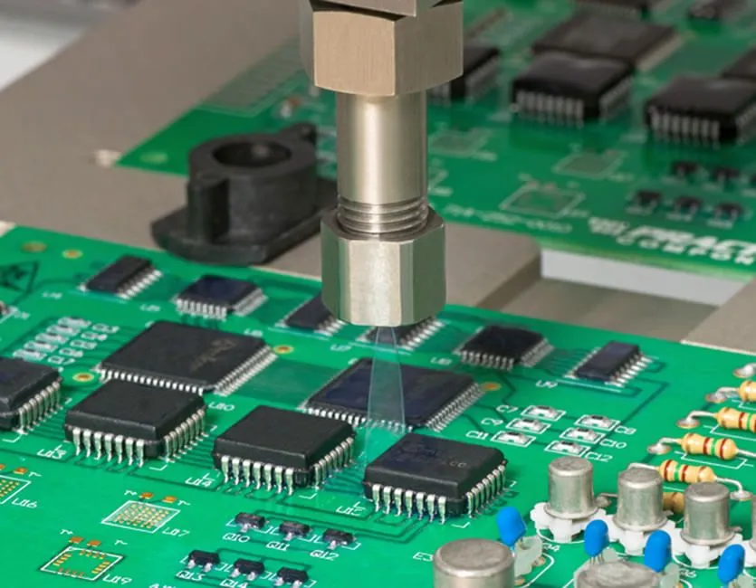
Conformal coating for wind turbines applies thin polymer films over assembled PCBs to enhance moisture and chemical resistance. Acrylic coatings offer easy rework and flexibility for vibration-prone areas, while urethane provides superior abrasion resistance. Silicone variants excel in wide temperature ranges but demand careful thickness control to avoid cracking. Application methods include selective spraying to coat high-risk areas like connectors without bridging fine-pitch components. Curing processes ensure uniform adhesion, tested per IPC-CC-830 for performance qualification. Proper masking protects terminations, maintaining solderability for field repairs.
Coating thickness typically ranges from 25 to 125 microns, verified through microscopic inspection post-application. Compatibility with flux residues prevents outgassing bubbles that compromise integrity. Rework procedures involve solvent stripping followed by residue removal to avoid contamination. Engineers select coatings based on site-specific threats, such as salt fog for offshore units. These steps integrate seamlessly into production flows for conformal coating for wind turbines.
Enhancing PCB Corrosion Resistance
PCB corrosion resistance starts with finish selection, favoring immersion tin or organic solderability preservatives over bare copper. Edge plating seals board perimeters against wicking. Salt spray exposure simulates marine conditions, guiding material choices. Anodized aluminum heatsinks resist pitting in humid cabinets. Assembly processes exclude halides to prevent activation sites. Multi-layered defenses ensure longevity.
Testing and Qualification Protocols
Environmental testing per IEC 60068 series validates PCB robustness through sequential stresses like temperature cycling and humidity storage. Vibration profiles mimic turbine spectra, checking for resonant failures. Thermal shock tests reveal coating adhesion flaws. Functional life testing under bias accelerates aging mechanisms. Qualification to IPC-6012E confirms manufacturing consistency for rigid boards. Data from these protocols refines iterative designs.
Troubleshooting Common Issues in Deployment
Engineers encounter intermittent faults from moisture-induced leakage currents, diagnosed via insulation resistance mapping. Vibration-loosened connectors require lock-wiring or conformal-coated threads. Thermal runaway in power stages signals inadequate via thermal reliefs. Corrosion creep traces back to incomplete solder mask coverage. Post-mortem analysis of failed units informs design updates, such as thicker coatings. Proactive monitoring via built-in telemetry predicts issues early.
Conclusion
Wind turbine control PCB design demands a holistic approach integrating material resilience, layout optimization, and protective measures. Prioritizing PCB environmental protection through enclosures, conformal coating for wind turbines, and rigorous testing yields systems that thrive in adversity. Adhering to wind turbine PCB design guidelines ensures compliance with high-reliability benchmarks. PCB corrosion resistance emerges from layered strategies rather than single solutions. Electric engineers can leverage these principles to deliver turbines with enhanced uptime and reduced lifecycle costs. Future advancements will further refine these practices for even harsher deployments.
FAQs
Q1: What are the primary wind turbine PCB design guidelines for offshore applications?
A1: Offshore wind turbine PCB design guidelines emphasize high-Tg laminates, ENIG finishes, and Class 3 fabrication to combat salt corrosion and humidity. Layouts incorporate wide power traces and vibration-damping mounts. Conformal coatings per industry specs seal assemblies against marine aerosols. Testing includes extended salt fog and thermal cycling to simulate 25-year service. These measures ensure reliable control functions in corrosive environments.
Q2: How does conformal coating improve PCB environmental protection in wind turbines?
A2: Conformal coating for wind turbines forms a dielectric barrier against moisture, chemicals, and particulates, preventing shorts and corrosion. Materials like urethane withstand abrasion from internal airflow while maintaining flexibility. Application thickness controls prevent cracking under thermal expansion. Qualification verifies adhesion and insulation post-stress. This protection extends MTBF in humid, vibrating nacelles.
Q3: Why is PCB corrosion resistance critical for wind turbine controls?
A3: PCB corrosion resistance prevents dendritic bridging and trace etching from salt and humidity, which cause control failures. Offshore exposure accelerates electrolytic action on exposed metals. Robust finishes and coatings mitigate these risks effectively. Designs incorporating edge seals enhance perimeter integrity. Reliable corrosion protection supports uninterrupted turbine operation.
Q4: What role do industry standards play in harsh environment PCB qualification?
A4: Standards like IPC-6012E define performance specs for rigid boards in demanding conditions. IEC 60068 outlines environmental test sequences for validation. Compliance ensures boards withstand cycling, vibration, and humidity. Engineers use these to benchmark designs objectively. Standardized approaches minimize field failures.
References
IPC-6012E — Qualification and Performance Specification for Rigid Printed Boards. IPC, 2020
IPC-CC-830C — Qualification and Performance of Electrical Insulating Compounds for Coating Printed Wiring Boards and Electronic Assemblies. IPC, 2011
IEC 60068 — Environmental testing. IEC, ongoing


