Introduction
Surgical robots rely on printed circuit boards (PCBs) to control precise movements, process sensor data, and power actuators during complex procedures. These PCBs often integrate high-power components like motor drivers and image processors that generate significant heat in compact spaces. Effective surgical robot PCB thermal management is essential to maintain operational reliability, as overheating can lead to performance degradation or system failures with direct implications for patient safety. Engineers must address heat dissipation early in the design phase to ensure consistent performance under prolonged use. This article explores key principles, strategies, and best practices for PCB heat dissipation tailored to surgical applications.
Why Thermal Management Matters in Surgical Robot PCBs
In surgical environments, PCBs operate continuously with minimal downtime, making thermal stability critical for sustained accuracy. Overheating accelerates component aging, increases leakage currents, and can cause delamination or solder joint failures. For instance, power electronics in robot arms must handle peak loads without exceeding safe operating temperatures. Poor PCB heat dissipation not only reduces lifespan but also compromises precision control signals sensitive to thermal noise. Adhering to high-reliability requirements amplifies the need for proactive thermal design.
Surgical robot PCB thermal management directly impacts overall system performance by preventing thermal runaway in densely packed boards. Heat buildup affects not just the generating components but also nearby analog circuits, leading to signal drift. Engineers prioritize this to meet stringent uptime demands in operating rooms. Ultimately, robust thermal strategies ensure the PCB supports the robot's dexterity and responsiveness without interruptions.
Fundamental Principles of Heat Transfer in Surgical Robot PCBs
Heat in PCBs arises primarily from power dissipation in components such as voltage regulators, FPGAs, and DC-DC converters used in surgical robots. This heat transfers via conduction through copper traces and planes, convection to surrounding air, and radiation, though the latter is minor at typical temperatures. Thermal resistance, measured in degrees Celsius per watt, quantifies the opposition to heat flow from junction to ambient. Understanding these paths allows engineers to model and mitigate hotspots effectively. Multilayer stacks enhance conduction by leveraging inner planes as heat spreaders.
In high-power PCB design, junction temperature remains the key metric, as it dictates reliability. Excessive temperatures degrade semiconductors and insulators over time. JEDEC standards provide frameworks for characterizing thermal performance under standardized conditions, aiding consistent evaluation. Convection relies on airflow or forced cooling, but passive methods dominate in sterile surgical settings to avoid contamination risks. Balancing these mechanisms prevents localized overheating that could warp boards or shift alignments.
Material and Stackup Strategies for Effective PCB Heat Dissipation
Selecting materials with balanced thermal conductivity and mechanical stability forms the foundation of PCB heat dissipation. Copper weight in outer and inner layers directly influences spreading efficiency, with heavier pours reducing trace temperatures. Multilayer configurations route heat vertically through planes while isolating signal layers. Engineers optimize stackups to minimize thermal gradients across the board. Vias and filled planes further bridge layers for uniform distribution.
High-power PCB design benefits from thicker dielectrics that maintain integrity under thermal stress, though thinner cores improve via performance. Inner plane cutouts prevent shorting while preserving heat paths. Fabricators align these choices with performance specs to avoid warpage. Overall, stackup planning integrates seamlessly with component needs for holistic thermal control.
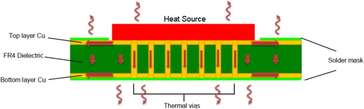
Leveraging Thermal Vias for Superior Heat Transfer
Thermal vias serve as vertical conduits, channeling heat from surface components to inner planes or the opposite side in surgical robot PCB thermal management. Placed in arrays under thermal pads, they lower effective thermal resistance by increasing cross-sectional area for conduction. Diameter, pitch, and plating thickness determine efficacy, with tenting or filling preventing solder wicking during assembly. IPC-2221 guidelines recommend strategic placement to avoid signal interference while maximizing dissipation. Arrays of 10-20 vias per square millimeter often suffice for moderate power.
Engineers simulate via farms to balance cost and performance, ensuring no voids compromise reliability. In high-power zones, staggered patterns enhance flow without hotspots. Post-assembly testing verifies functionality through temperature mapping. These elements make thermal vias indispensable for compact designs.
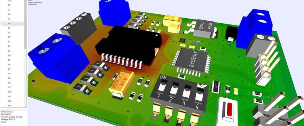
Optimizing Component Placement for Heat Reduction
Component placement for heat reduction starts with segregating high-power devices from sensitive analog and RF sections. Positioning heat sources near board edges facilitates edge cooling or chassis attachment. Uniform distribution across the PCB prevents localized hotspots that could affect nearby passives. Minimum spacing around power components allows airflow and reduces convective interference. Simulation tools reveal optimal layouts before prototyping.
In surgical robot applications, motor drivers cluster on dedicated power planes, isolated by ground pours acting as barriers. Sensitive sensors locate on cooler inner layers. This approach aligns with high-power PCB design principles, enhancing overall thermal uniformity. Troubleshooting involves iterating placements based on empirical data.
Advanced Techniques in High-Power PCB Design
High-power PCB design incorporates wide traces sized per IPC-2152 for current capacity, minimizing I-squared-R losses. Copper pours under components act as integrated heatsinks, coupled with vias for three-dimensional spreading. Passive elements like thermal pads interface components to chassis without active fans. Multiboard systems share heat loads via connectors. These methods ensure compliance with reliability classes for medical use.
Embedded structures, such as metal cores, boost conductivity in extreme cases, though they add complexity. Surface finishes with good solderability support robust thermal interfaces. Validation through accelerated testing confirms margins. Practical implementation focuses on manufacturability alongside performance.
Troubleshooting Thermal Issues in Surgical Robot PCBs
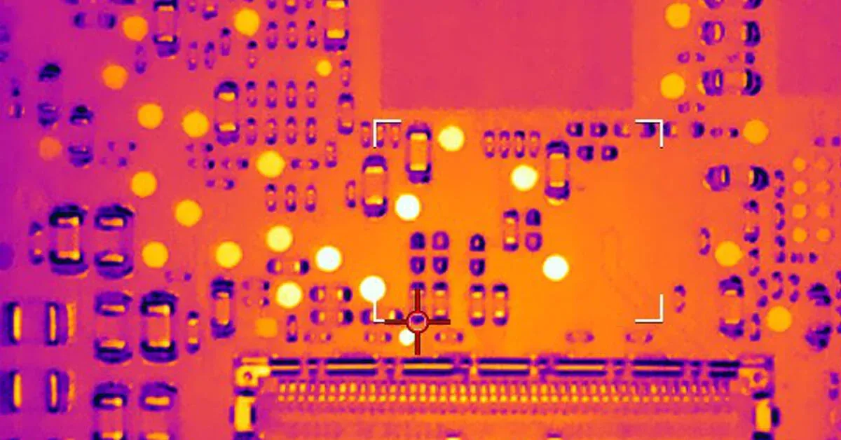
Common pitfalls include inadequate via density leading to pad overheating or trace necking from thermal expansion. Engineers diagnose via infrared imaging during operation, correlating with simulations. Warpage from asymmetric heating requires balanced stackups. Solder joint cracking under cyclic loads signals insufficient dissipation. Iterative prototyping resolves these, prioritizing root causes.
Over-spec'd components mask underlying flaws temporarily. Board-level shielding contains EMI while aiding convection. Field returns often trace to overlooked hotspots near connectors. Proactive monitoring sustains long-term performance.
Conclusion
Surgical robot PCB thermal management demands integrated strategies from stackup to placement, ensuring PCBs withstand demanding conditions. Thermal vias, optimized layouts, and robust materials drive effective heat dissipation. High-power PCB design principles, guided by standards, prevent failures and uphold precision. Engineers applying these practices deliver reliable systems for critical applications. Prioritizing thermal integrity from concept to deployment secures performance and safety.
FAQs
Q1: What role do thermal vias play in surgical robot PCB thermal management?
A1: Thermal vias transfer heat vertically from components to inner planes, reducing junction temperatures in compact designs. Arrays under power pads enhance conduction without enlarging footprints. Proper sizing and filling prevent assembly issues while complying with design guidelines. This approach is vital for high-density boards in robots, maintaining reliability during extended surgeries.
Q2: How does component placement for heat reduction improve PCB heat dissipation?
A2: Strategic placement spaces high-power components from sensitive circuits, promoting even heat distribution and airflow. Locating sources near edges aids chassis cooling. Simulations guide layouts to minimize gradients. In surgical robots, this prevents signal interference and extends component life, optimizing overall thermal performance.
Q3: What are key considerations in high-power PCB design for surgical applications?
A3: High-power PCB design focuses on thick copper traces, multilayer planes, and thermal interfaces to handle currents without excessive heating. Standards like IPC-2152 size conductors accurately. Isolation and spreading prevent hotspots. These ensure stable operation in precision environments, avoiding failures mid-procedure.
Q4: Why is PCB heat dissipation critical in surgical robots?
A4: Effective PCB heat dissipation prevents overheating that degrades performance, accuracy, and safety. Compact layouts amplify risks from power electronics. Proactive management sustains reliability under continuous use. Troubleshooting hotspots early avoids costly redesigns and downtime.
References
IPC-2221 — Generic Standard on the Design of Rigid Printed Boards. IPC.
IPC-2152A — Standard for Determining Current Carrying Capacity in Printed Board Design. IPC.
JEDEC JESD51-2A — Integrated Circuits Thermal Test Method Environmental Conditions - Natural Convection (Still Air). JEDEC.


