Introduction
In critical applications such as aerospace systems, medical devices, and high-reliability telecommunications equipment, electrical engineers demand exceptional precision from every component on a printed circuit board. Buried resistors, embedded directly within PCB layers, offer a pathway to achieve buried resistor tolerance levels that surpass traditional surface-mount options in space-constrained designs. These high-precision resistors integrate seamlessly into the board structure, minimizing parasitics and enhancing signal integrity. However, walking the tolerance tightrope requires mastering manufacturing variables, material selection, and post-fabrication adjustments. This article explores the engineering principles behind buried resistor tolerance, pcb resistor tolerance management, and strategies for resistor value control in demanding environments. Engineers can leverage these insights to optimize performance while adhering to rigorous industry standards.
Understanding Buried Resistors and Their Role in Precision Design
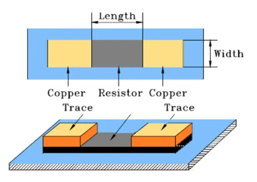
Buried resistors represent an advanced embedded passive technology where resistive material is laminated between PCB layers, forming part of the interconnect structure itself. Unlike discrete surface-mount resistors, buried resistors eliminate solder joints and exposed elements, reducing assembly defects and improving long-term reliability. This integration is particularly valuable in multilayer boards where board real estate is at a premium. The core challenge lies in controlling pcb resistor tolerance during fabrication, as initial sheet resistance variations can impact final values. High-precision resistors demand careful process control to meet circuit requirements in analog filters, feedback networks, and precision amplifiers. By embedding resistors, designers achieve compact layouts without compromising electrical performance.
The relevance of buried resistors amplifies in critical applications where even minor tolerance drifts can cascade into system failures. For instance, in avionics or implantable medical devices, stringent pcb resistor tolerance ensures stable operation under thermal cycling and vibration. Industry standards like IPC-4811 outline specifications for embedded passive device resistor materials, guiding material selection for consistent performance. Engineers must weigh the trade-offs between initial tolerance, which may be broader due to lamination stresses, and the potential for refinement. This balance defines why buried resistors matter: they enable high-density, high-reliability designs unattainable with conventional components.
Technical Principles of Buried Resistor Fabrication and Tolerance
Buried resistors typically employ thin-film resistive foils, such as nickel-phosphorus alloys, bonded to copper layers during the PCB lamination process. These materials exhibit stable temperature coefficients and sheet resistances tailored for specific value ranges. Initial resistor values emerge from the geometry defined in design, including length, width, and thickness, but fabrication tolerances introduce variability from etching, plating, and thermal expansion mismatches. Buried resistor tolerance starts broader post-lamination, often necessitating adjustments to achieve precision. Key mechanisms include controlling foil thickness uniformity and minimizing substrate warpage, which directly influence final resistance stability.
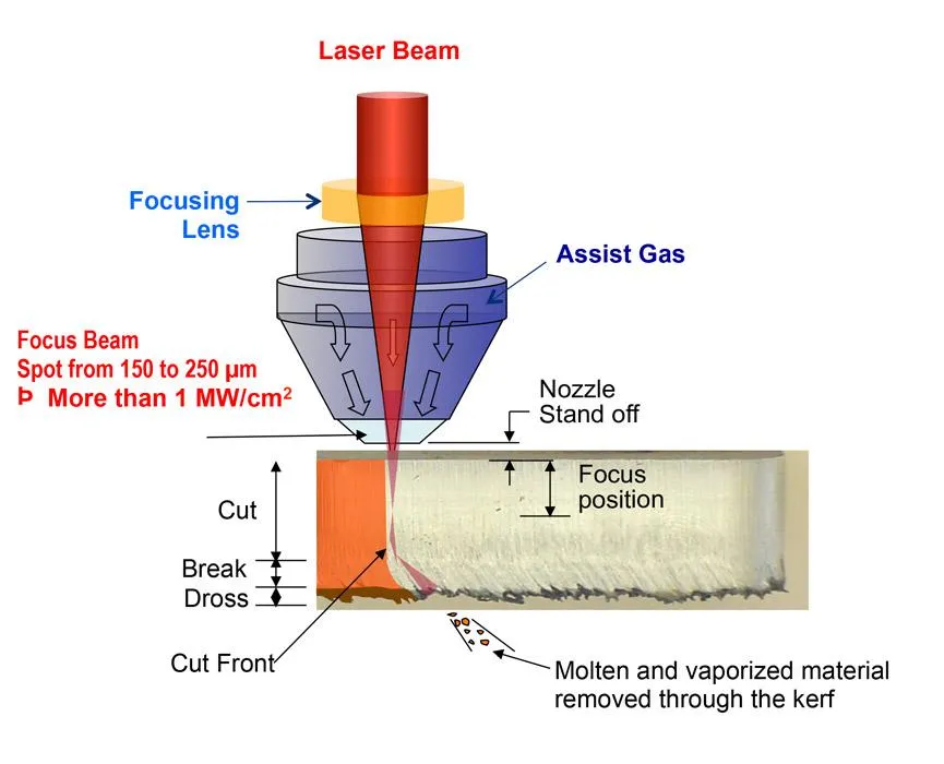
Laser trimming emerges as the cornerstone of buried resistor trimming, a process where a focused beam precisely removes material to fine-tune resistance. Performed after lamination but before final encapsulation, this technique allows for resistor value control down to levels suitable for precision circuits. Engineers model the trimming path using serpentine, L-cut, or plunge patterns to predict value shifts accurately. Factors like beam power, speed, and ambient conditions must align to avoid microcracks or thermal damage. IPC-2221B provides generic guidelines for printed board design, including embedded elements, emphasizing layout rules that support effective trimming. Understanding these principles equips designers to specify geometries that facilitate tight buried resistor tolerance.
Environmental stability further hinges on the resistor's interaction with surrounding dielectrics and conductors. Thermal coefficient of resistance (TCR) values, inherent to the material, dictate drift under operating temperatures. Mechanical stresses from board flexing or CTE mismatches can alter contact resistance at terminations. High-precision resistors require qualification per standards like IPC-6017, which specifies performance for boards with embedded passives. Engineers simulate these effects using finite element analysis to predict tolerance shifts over lifecycle.
Best Practices for Achieving Precision in Buried Resistor Implementation
Selecting appropriate resistive materials compliant with IPC-4811 ensures a foundation for reliable buried resistor tolerance. Engineers should specify sheet resistance values matching target ranges, typically spanning low to medium ohms per square, and verify supplier data for TCR consistency. Design rules call for adequate termination pads to minimize contact resistance variability and isolation from high-current traces to prevent thermal runaway. Incorporating test points or coupons on panel borders aids in-process monitoring of pcb resistor tolerance. Multilayer stackups must balance core and prepreg thicknesses to control lamination pressures uniformly.
Buried resistor trimming demands a structured workflow, starting with electrical mapping of as-laminated values using flying probe testers. Algorithms then compute optimal trim paths, accounting for kerf width and resistance delta per unit length. Post-trim verification confirms value stability under bias and temperature, aligning with high-precision resistors requirements. Process controls include cleanroom handling to avoid contamination and calibrated optics for laser accuracy. For resistor value control in production, statistical process control tracks CpK metrics across lots. Avoiding over-trimming preserves long-term drift performance.
Quality assurance extends to environmental stress screening, simulating operational extremes to validate tolerance retention. IPC-6017 outlines qualification tests like thermal cycling and humidity exposure for embedded devices. Engineers integrate design for testability by routing access vias for in-circuit measurement post-assembly. Troubleshooting common issues, such as value drift from via drilling proximity, involves iterative stackup reviews. These practices collectively tighten the tolerance tightrope, enabling deployment in critical applications.
Troubleshooting Tolerance Variations in Buried Resistors
Engineers often encounter buried resistor tolerance deviations traced to lamination voids or etch undercut. Inspecting cross-sections reveals delamination at resistive foil interfaces, prompting adjustments in press cycles. Trimming inconsistencies arise from focal drift, resolved by real-time feedback loops in laser systems. Pcb resistor tolerance tightens with optimized exposure development, ensuring crisp resistor outlines. In one engineering scenario, a high-frequency RF module exhibited gain instability due to 5% value spreads; root cause analysis linked it to prepreg flow imbalances, corrected via material swaps.
Another frequent challenge involves TCR mismatches in mixed-value arrays, amplifying thermal sensitivities. Calibration using temperature-controlled chambers refines predictions. Proximity to power planes induces self-heating, mitigated by ground shielding. Buried resistor trimming post-drill can address via-induced shorts, though preemptive spacing per IPC-2221B prevents this. Documenting these fixes in design libraries accelerates future iterations.
Conclusion
Mastering buried resistor tolerance demands a holistic approach from material selection through qualification, balancing fabrication realities with precision needs. High-precision resistors via embedded technology offer compelling advantages in critical applications, provided engineers adhere to standards like IPC-4811, IPC-6017, and IPC-2221B. Buried resistor trimming and resistor value control techniques enable tolerances rivaling discrete components while enhancing board density and reliability. By implementing structured design and process controls, electrical engineers can confidently navigate the tolerance tightrope. Future advancements in materials and automation promise even tighter pcb resistor tolerance, solidifying buried resistors' role in next-generation electronics.
FAQs
Q1: What factors primarily influence buried resistor tolerance in PCBs?
A1: Buried resistor tolerance depends on resistive foil uniformity, lamination pressures, and etching precision during fabrication. Post-lamination variations from thermal expansion require buried resistor trimming for refinement. Adhering to IPC-4811 for material specs minimizes initial spreads, while design geometries aid resistor value control. Engineers achieve high-precision resistors by integrating test coupons for lot monitoring.
Q2: How does buried resistor trimming improve pcb resistor tolerance?
A2: Buried resistor trimming uses laser ablation to adjust resistance values after lamination, compensating for process-induced variations. This enables tighter tolerances essential for analog precision circuits. Patterns like L-cuts provide predictable control, verified via in-situ measurements. Overall, it transforms broad initial pcb resistor tolerance into stable performance under operational stresses.
Q3: Why are high-precision resistors critical in applications using buried resistors?
A3: High-precision resistors ensure signal fidelity in feedback loops and filters within aerospace and medical PCBs. Buried implementations reduce parasitics compared to surface-mount, but demand rigorous resistor value control. Standards like IPC-6017 qualify stability post-trimming. Engineers prioritize them for reliability in vibration-prone environments.
Q4: What design best practices enhance resistor value control for buried resistors?
A4: Specify isolated geometries with robust terminations to stabilize buried resistor tolerance. Include trim access and coupons per IPC-2221B guidelines. Simulate TCR effects early to predict drifts. These steps optimize manufacturing yield and long-term precision.
References
IPC-4811 - Specification for Embedded Passive Device Resistor Materials for Rigid and Multilayer Printed Boards. IPC, 2008
IPC-6017 - Qualification and Performance Specification for Printed Boards Containing Embedded Passive Devices. IPC, 2009
IPC-2221B - Generic Standard on Printed Board Design. IPC, 2012