Introduction
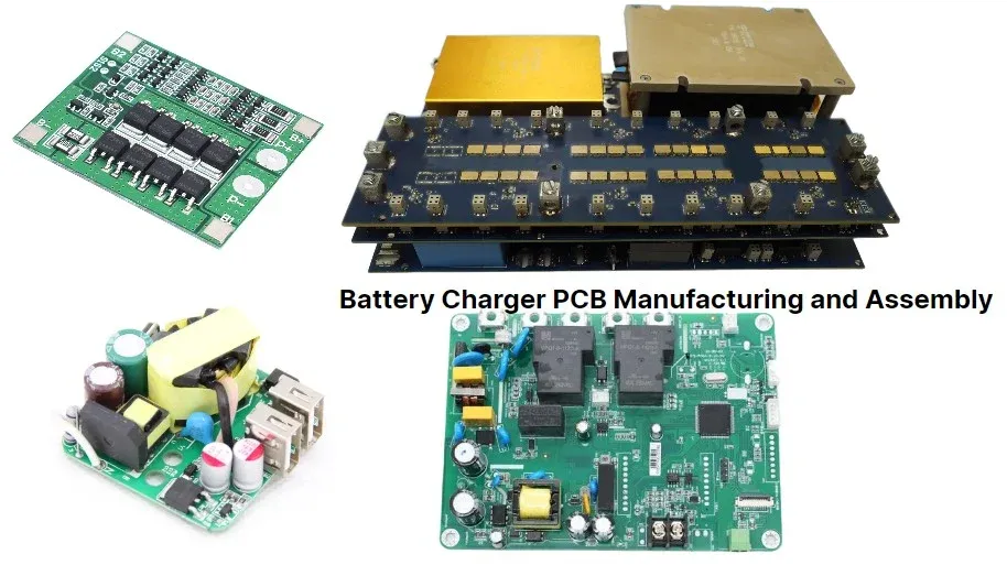
Battery charger printed circuit boards (PCBs) form the backbone of reliable power delivery in devices ranging from consumer electronics to industrial equipment. These boards manage complex tasks like current regulation, voltage control, and thermal protection under demanding electrical loads. When issues arise, such as no output, overheating, or failure to charge, engineers must pinpoint faults efficiently to minimize downtime. Battery charger PCB troubleshooting requires a methodical approach, combining visual checks with electrical measurements. This practical guide targets electric engineers, offering step-by-step strategies for diagnosing short circuit PCB problems, open circuit PCB faults, component failure PCB scenarios, and PCB repair techniques. Mastering these skills ensures safer, longer-lasting charger performance.
Why Battery Charger PCB Troubleshooting Matters
Reliable battery chargers prevent overcharging, shorting, or thermal runaway, which can damage batteries or pose fire risks. In high-volume production or field service, undetected PCB faults cascade into system-wide failures, increasing warranty claims and repair costs. Electric engineers benefit from proactive troubleshooting to maintain compliance with safety norms and optimize designs. Common symptoms like blown fuses, erratic voltage output, or no LED indicators signal underlying PCB issues that demand immediate attention. Addressing these early extends product lifespan and supports iterative improvements in charger circuitry. Ultimately, effective diagnostics align with engineering best practices for robust power electronics.
Common Causes of Failures in Battery Charger PCBs
Battery charger PCBs endure stresses from high currents, switching frequencies, and heat dissipation, leading to predictable failure modes. Manufacturing defects, such as inadequate solder joints or trace delamination, often initiate problems during operation. Environmental factors like humidity accelerate corrosion on exposed pads or vias, compromising connectivity. Component mismatches, including incorrect ratings for diodes or capacitors, exacerbate issues under load. Over time, thermal cycling causes mechanical fatigue in solder connections, resulting in intermittent faults. Understanding these mechanisms guides targeted battery charger PCB troubleshooting.
Short Circuit PCB Issues
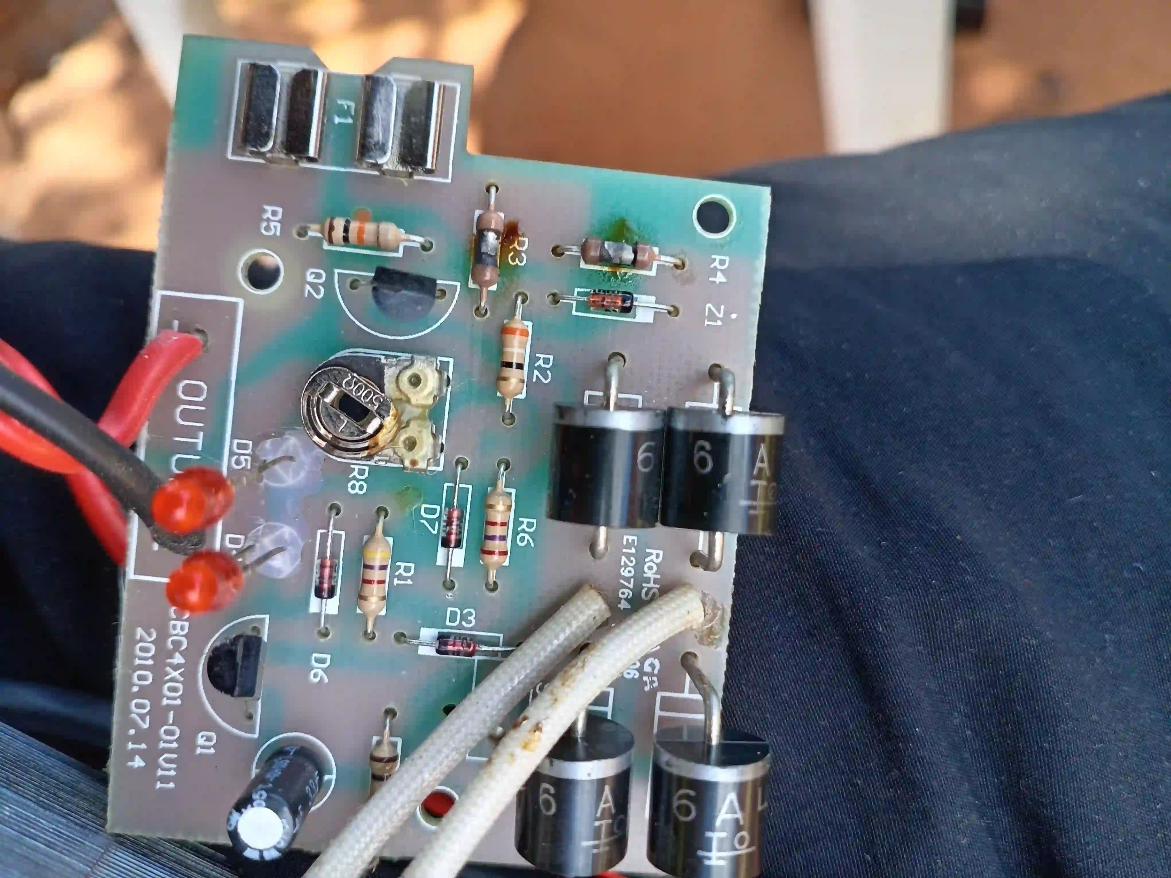
Short circuit PCB failures in battery chargers typically manifest as immediate fuse blowing or excessive current draw upon power-up. Solder bridges between adjacent pads create unintended paths, bypassing critical components like rectifiers or MOSFETs. Damaged traces from mechanical stress or manufacturing burrs can short to ground planes, pulling down supply rails. In charger circuits, these faults overload protection diodes, leading to rapid heating. Visual signs include scorch marks or discolored copper. Engineers should isolate power and use a multimeter in continuity mode to probe suspect areas during diagnosis.
Short circuits often stem from assembly errors, where excess solder wicks across fine-pitch components. High-power sections, such as input rectifiers, amplify risks due to elevated temperatures melting nearby joints. Probing with an ohmmeter reveals resistances below expected values, confirming the fault. Debris like flux residue can also form conductive paths post-reflow. Clearing these requires isopropyl alcohol cleaning followed by rework. Preventing recurrence involves strict process controls aligned with soldering standards.
Open Circuit PCB Problems
Open circuit PCB faults prevent current flow, resulting in no-charge conditions or dead output stages in battery chargers. Cracked traces from board flexing during handling interrupt signal paths to charging ICs. Cold solder joints, lacking proper wetting, create high-resistance connections that fail under vibration. Lifted pads from repeated rework weaken mechanical bonds, opening circuits intermittently. Vias clogged with debris block interlayer connections in multilayer boards. Symptoms include zero voltage at test points despite input power.
Diagnosis starts with continuity testing across traces from input to output. Magnification reveals hairline fractures invisible to the naked eye. Thermal imaging highlights intermittent opens that close under heat. Repair involves jumper wires or trace recoating with conductive epoxy for temporary fixes. Permanent solutions demand board replacement if warpage exceeds limits. Engineers verify fixes by loading the circuit and monitoring waveforms.
Component Failure PCB Analysis
Component failure PCB issues dominate battery charger troubleshooting, with capacitors, diodes, and ICs bearing the brunt of electrical stress. Electrolytic capacitors swell or leak from ripple current overload, altering feedback loops. Schottky diodes short from reverse voltage spikes, blocking rectification. Charging controller ICs burn out due to inadequate heatsinking or overvoltage transients. Resistors crack from power dissipation beyond ratings, shifting bias points. Identifying failed parts requires datasheets for expected parameters.
In-circuit testing with an LCR meter flags out-of-tolerance values without desoldering. Diode checks confirm forward bias drops around 0.3 to 0.7 volts. Oscilloscope captures switching anomalies pointing to gate drive failures. Thermal cameras spot hot spots before total breakdown. Replacement demands matching specs for voltage, current, and package. Post-repair bake-out stabilizes new parts.
According to IPC-A-610 acceptability criteria, engineers assess joint integrity to avoid reintroducing weaknesses.
Systematic Troubleshooting Techniques
Battery charger PCB troubleshooting begins with safety: discharge capacitors and unplug power sources. Visual inspection under 10x magnification uncovers 70 percent of faults like bridges or cracks. Power on with current-limited supply to observe draw patterns. Multimeter verifies DC rails against expected levels from schematics. Continuity maps nets from power entry to battery output. Isolate sections by lifting legs to divide-and-conquer.
For dynamic faults, scope probes PWM signals and ripple on outputs. Logic analyzers decode communication buses in smart chargers. Environmental chambers simulate heat to provoke latent issues. Document findings in a fault tree for root cause analysis. This layered approach resolves most cases without board swaps.
PCB Repair Best Practices
Effective PCB repair restores functionality while preserving integrity. Hot air rework stations remove and replace SMD parts precisely. Solder wick cleans bridges without trace damage. Conductive silver pens bridge opens temporarily. Reflow profiles match original processes to avoid tombstoning. Bake boards post-repair to outgas moisture. For precise solder paste deposition during rework, see our guide to SMT stencils for rework and repair.
Adherence to J-STD-001 soldering requirements ensures reliable joints with proper fillet formation. Conformal coating protects repaired areas from humidity. Test under full load and temperature cycles before deployment. Track repair data to inform design revisions, like wider traces or better spacing.
Advanced Diagnostics for Persistent Issues
When basic tests fail, X-ray inspection reveals subsurface voids or bridging in BGAs. Flying probe testers automate netlist verification without fixtures. Spectrum analyzers detect EMI signatures of arcing. Finite element analysis models thermal stresses for prediction. Collaborate with fabs for process audits if systemic.
IPC-6012 performance specifications guide qualification of repaired boards for high-reliability apps. These tools elevate troubleshooting from reactive to preventive.
Conclusion
Battery charger PCB troubleshooting demands precision to tackle short circuit PCB, open circuit PCB, and component failure PCB challenges head-on. Electric engineers armed with visual, electrical, and thermal diagnostics restore chargers efficiently. Prioritizing standards and best practices minimizes recurrence and boosts reliability. Regular maintenance and design feedback loops yield durable solutions. Apply these techniques to enhance your power electronics expertise.
FAQs
Q1: How do I start battery charger PCB troubleshooting for a no-charge symptom?
A1: Inspect for blown fuses or obvious damage first, then check input voltage and continuity to the charging IC. Measure output rails with a multimeter under no load. Scope ripple if DC is present but charging fails. Isolate sections to narrow faults. This systematic PCB repair approach resolves most open circuit PCB issues quickly.
Q2: What causes short circuit PCB failures in battery chargers?
A2: Solder bridges, trace-to-plane shorts, or failed diodes create low-resistance paths drawing excessive current. Manufacturing flux residue or mechanical damage contributes. Visual checks and ohmmeter tests confirm. Clean and rework per soldering standards to fix.
Q3: How to diagnose component failure PCB in chargers?
A3: Use in-circuit ESR for capacitors, diode tests for rectifiers, and thermal imaging for hot ICs. Compare readings to datasheets. Desolder suspects for bench testing. Replace with rated equivalents and verify under load.
Q4: What are best practices for PCB repair after troubleshooting?
A4: Follow controlled rework profiles, clean flux thoroughly, and apply stress relief bends on jumpers. Test thermally cycled units. Document for traceability to prevent repeat component failure PCB problems.
References
IPC-A-610H — Acceptability of Electronic Assemblies. IPC, 2019
IPC J-STD-001H — Requirements for Soldered Electrical and Electronic Assemblies. IPC, 2018
IPC-6012DS — Qualification and Performance Specification for Rigid Printed Boards. IPC, 2015


