Introduction
Power supply printed circuit boards (PCBs) form the backbone of reliable electrical systems, handling high currents, voltages, and thermal stresses that demand stringent safety and performance criteria. Certifications such as power supply PCB UL, CE, and RoHS ensure these boards meet regulatory requirements for safety, electromagnetic compatibility, and environmental protection. For electric engineers designing or specifying power supplies, grasping these certifications prevents field failures, facilitates market access, and aligns with global compliance needs. These standards address risks like fire hazards, electrical shock, and hazardous material exposure inherent in power electronics. Understanding power supply PCB certifications empowers engineers to select materials and processes that balance performance with regulatory adherence from the outset.
Why Power Supply PCB Certifications Matter
Power supply PCBs operate under demanding conditions, including elevated temperatures, voltage gradients, and power densities that amplify failure risks such as arcing or insulation breakdown. Certifications verify that boards withstand these stresses without compromising user safety or system integrity, which is critical for applications in industrial controls, medical devices, and consumer electronics. Without proper power supply PCB UL, CE, or RoHS compliance, products face legal barriers, recalls, or liability issues in regulated markets. Engineers benefit from these certifications by gaining confidence in supplier capabilities and reducing design iterations during qualification testing. Moreover, they promote interoperability across supply chains, ensuring consistent quality from fabrication to end-use.
In high-reliability sectors, non-compliant PCBs can lead to cascading failures, such as trace delamination under thermal cycling or solder joint degradation from incompatible materials. Certifications enforce traceability, from base laminate selection to final assembly, fostering trust among stakeholders. For electric engineers, this translates to fewer prototypes rejected during type approval and smoother transitions to volume production.
Key Power Supply PCB Certifications Explained
Power Supply PCB UL Certification
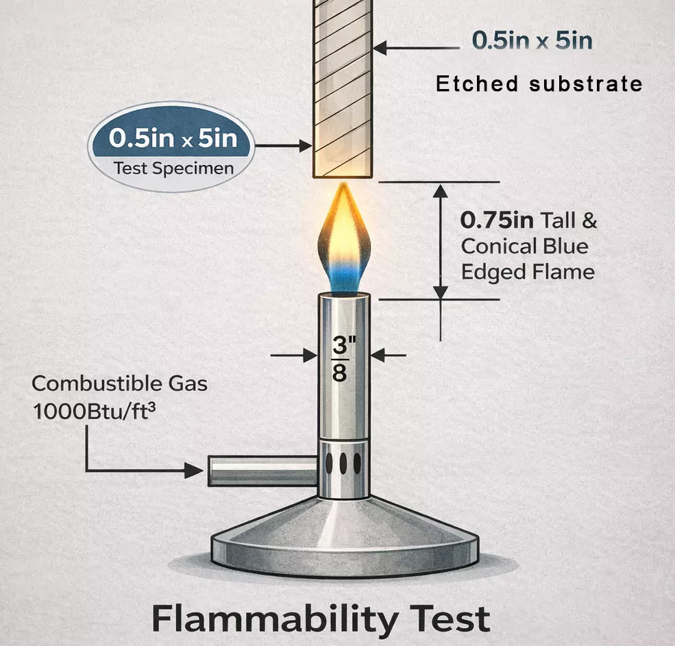
Power supply PCB UL certification focuses on safety aspects, particularly flammability, electrical spacing, and material endurance under electrical stress. It evaluates the PCB's construction to prevent ignition sources and ensure insulation reliability in power applications. Engineers must consider factors like comparative tracking index (CTI) for creepage paths and relative thermal index (RTI) for polymers, which dictate minimum clearances between high-voltage traces. UL-recognized PCBs undergo rigorous testing for vertical flammability per established protocols, confirming they self-extinguish without propagating fire.
This certification applies at both component and system levels, requiring manufacturers to maintain controlled processes for consistent output. For power supplies, UL compliance often involves specifying laminates with defined glass transition temperatures and dielectric strengths to handle voltage spikes. Electric engineers integrate these parameters early in schematic capture and layout to avoid costly redesigns.
Power Supply PCB CE Marking
CE marking for power supply PCBs signifies conformity with European Union directives, including Low Voltage Directive (LVD), Electromagnetic Compatibility (EMC) Directive, and RoHS. Unlike third-party testing, CE often relies on manufacturer self-declaration after internal assessments against harmonized standards for safety and emissions. For PCBs in power supplies, this means verifying insulation coordination, ground bonding, and radiated emissions from switching circuits. Engineers address CE by simulating field strengths and optimizing ground planes to suppress noise coupling.
Compliance documentation includes risk assessments and technical files detailing PCB stackup, via plating, and solder mask properties. Power supply designs must demonstrate fault tolerance, such as overcurrent protection integration, to meet LVD requirements. This holistic approach ensures the PCB contributes to overall product EMC without necessitating separate module certification.
Power Supply PCB RoHS Compliance
RoHS compliance restricts hazardous substances like lead, mercury, cadmium, hexavalent chromium, polybrominated biphenyls (PBB), and polybrominated diphenyl ethers (PBDE) in PCBs to protect health and environment. For power supply applications, this mandates lead-free finishes such as ENIG or OSP, alongside halogen-free laminates to avoid toxicity during reflow or disposal. Engineers select materials with verified substance declarations, monitoring thresholds typically at 0.1% by weight for most items and 0.01% for cadmium.
Achieving RoHS involves supply chain audits and process controls to prevent contamination, especially in multi-layer boards with inner layer foils. Thermal profiles adjust for higher melting points of lead-free alloys, influencing via fill and pad cratering risks. Compliance enhances recyclability and aligns with global trends toward sustainable electronics manufacturing.
Technical Principles Behind Certifications
Certifications hinge on material properties and fabrication tolerances that govern electrical, thermal, and mechanical behaviors in power supplies. For instance, dielectric breakdown strength ensures trace-to-trace isolation under overvoltages, while copper weight uniformity prevents hot spots in high-current paths. IPC-6012 qualification specifications outline performance classes for rigid boards, emphasizing bow and twist limits critical for component mounting in power modules. Testing protocols simulate operational extremes, revealing weaknesses like microvoids in plating that could escalate to arcing.
Flammability ratings classify materials by burn rate and drip characteristics, directly impacting UL suitability for enclosed power supplies. Creepage and clearance distances scale with pollution degrees and overvoltage categories, requiring precise routing algorithms during layout. J-STD-001 requirements for soldered assemblies dictate cleanliness levels to avert dendritic growth in humid environments.
Environmental stability ties into RoHS through polymer formulations resistant to hydrolysis, preserving insulation resistance over lifecycle. Engineers model these using finite element analysis for thermal gradients across multilayer stacks. Adherence to these principles minimizes field returns and extends mean time between failures.
Best Practices for Achieving Compliance
Select laminates with certified flammability (V-0 or better) and high CTI (>600V) suited to power supply pollution environments. Collaborate with fabricators holding process controls aligned with IPC Class 3 for high-reliability boards. Implement design rules enforcing minimum clearances per working voltage, incorporating pollution degree factors for CE and UL.
During procurement, request material data sheets confirming RoHS substance lists and UL file numbers. Prototype testing should include thermal cycling per IPC-6012 to validate warpage under power dissipation. For assembly, enforce lead-free profiles with peak temperatures controlled to prevent intermetallic compound formation.
Document stackups, drill files, and fab drawings with compliance annotations for audit trails. Conduct in-house EMC scans early to iterate ground partitioning before CE declaration. Regular supplier audits ensure ongoing material traceability, mitigating risks from raw material fluctuations.
Common Challenges and Troubleshooting
High-power densities often induce thermal gradients causing delamination, addressed by thicker cores and embedded vias for heat spreading. RoHS-mandated lead-free solders raise voiding risks in BGAs, mitigated via nitrogen reflow atmospheres and optimized ramp rates. UL spacing violations arise from dense layouts; engineers resolve this with split planes and guard traces.
EMC issues in switching power supplies stem from parasitic inductances; troubleshooting involves ferrite beads and snubbers per CE EMC standards. Humidity-induced failures challenge insulation; conformal coatings with verified RTI extend compliance. Proactive DFM reviews catch these early, saving iteration costs.
Conclusion
Power supply PCB certifications like UL, CE, and RoHS form essential safeguards, ensuring safety, market access, and sustainability in demanding applications. Electric engineers who integrate these from design inception achieve robust, compliant products with minimal rework. By aligning processes with IPC and related specifications, teams enhance reliability across the product lifecycle. Prioritizing these standards not only meets regulatory demands but also drives innovation in efficient power electronics.
FAQs
Q1: What does power supply PCB UL certification entail?
A1: Power supply PCB UL certification verifies safety through tests on flammability, electrical spacing, and material durability under stress. It covers aspects like UL 94 vertical burn ratings and CTI for creepage paths, ensuring boards resist ignition in high-voltage environments. Engineers use it to qualify laminates and constructions for power applications, reducing fire and shock hazards. Compliance requires manufacturer file numbers for traceability.
Q2: How does power supply PCB CE marking apply to designs?
A2: Power supply PCB CE marking confirms adherence to EU directives via self-declaration after LVD, EMC, and RoHS assessments. It demands optimized layouts for emissions control and insulation per harmonized standards. Electric engineers document PCB contributions to system conformity, including ground integrity and fault protection. This facilitates EU market entry without third-party hurdles.
Q3: Why is power supply PCB RoHS compliance critical for engineers?
A3: Power supply PCB RoHS compliance limits hazardous substances, mandating lead-free processes and verified materials. It prevents environmental harm while addressing higher reflow challenges in multilayer boards. Engineers select compliant finishes like ENIG to avoid reliability issues like whisker growth. This ensures global sustainability and supply chain acceptance.
Q4: What role do standards play in power supply PCB certifications?
A4: Standards like IPC-6012 guide qualification for performance under thermal and mechanical stresses relevant to UL and CE. They define acceptability criteria for fabrication, aiding consistent compliance. J-STD-001 ensures soldering quality for RoHS lead-free assemblies. Engineers reference them for DFM to streamline certification paths.
References
IPC-6012E - Qualification and Performance Specification for Rigid Printed Boards. IPC, 2017
IPC-A-600K - Acceptability of Printed Boards. IPC, 2020
J-STD-001G - Requirements for Soldered Electrical and Electronic Assemblies. IPC, 2017


