Introduction
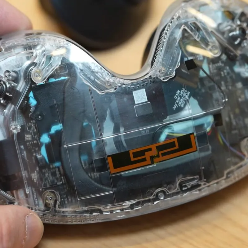
VR headset PCB assembly presents unique challenges due to the need for compact designs packed with high-density components, sensors, and processors. Engineers must balance miniaturization with mechanical reliability, as these devices endure constant motion, heat generation, and user handling. Surface mount technology (SMT) dominates for its efficiency in placing tiny chips, while through-hole technology (THT) remains essential for robust connectors and power components. Proper VR headset PCB assembly minimizes defects like solder joint failures that could disrupt immersive experiences. This article explores best practices for both SMT assembly VR PCB processes and through-hole assembly VR headset techniques, focusing on practical steps to achieve high yields. By following these guidelines, teams can produce assemblies that meet demanding performance standards.
Why VR Headset PCB Assembly Matters
VR headsets rely on PCBs that support high-speed data transmission for displays, tracking sensors, and wireless modules, making assembly precision critical. Poor VR headset PCB assembly can lead to intermittent failures, such as signal loss or overheating, which degrade user immersion and device lifespan. SMT enables the small form factors required, but THT provides the mechanical strength for batteries and interfaces subjected to vibrations. Industry demands push for mixed-technology boards where both methods coexist, amplifying risks like thermal stress during processing. Addressing these ensures compliance with reliability benchmarks and reduces field returns. Ultimately, effective practices in VR headset PCB assembly directly impact product quality and market success.
Technical Principles of SMT and Through-Hole in VR Headsets
SMT involves printing solder paste on pads, placing components, and reflowing to form joints, ideal for the fine-pitch ICs in VR headsets. Components sit directly on the board surface, allowing double-sided population and higher density compared to THT. Reflow soldering VR PCB requires controlled heating to melt paste without damaging sensitive parts like IMUs or optics drivers. Through-hole assembly VR headset uses drilled holes for leads that extend to the opposite side, soldered via wave or selective methods for superior strength. In mixed boards, SMT precedes THT to avoid disturbing surface mounts during insertion. Thermal expansion differences between materials can cause warpage, a key concern in multilayer VR designs that must be addressed through high-performance PCB assembly strategies. Understanding these key design considerations ensures that density gains in VR headsets do not compromise long-term structural integrity or yield rates.
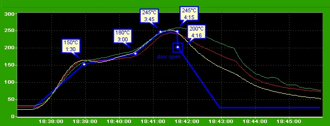
The reflow process follows a profile with preheat, soak, reflow, and cool-down phases to ensure uniform melting. JEDEC J-STD-020E outlines moisture sensitivity classifications that guide handling before reflow soldering VR PCB. THT principles emphasize hole-to-lead fit, typically with slight clearance for easy insertion without stressing pads. Wave soldering floods the underside with molten solder, wicking up leads for barrel fills. Engineers must account for VR-specific stressors like rapid thermal cycling from processor loads. Understanding these mechanisms prevents common pitfalls in high-volume production.
Best Practices for SMT Assembly in VR PCBs
Start with precise stencil design for solder paste printing, ensuring aperture sizes match pad geometry to avoid insufficient or excess deposit. Use high-precision printers with vision alignment for fine-pitch components common in VR headsets. Component placement demands accuracy below 50 microns to prevent shifts during reflow. Verify feeder setups and nozzle calibration to handle varied package sizes like QFNs and BGAs. Pre-reflow inspection via SPI catches paste volume issues early. These steps form the foundation of reliable SMT assembly VR PCB, effectively addressing the complex design considerations and challenges of PCB assembly for high-frequency applications.
Optimize reflow oven profiles to match component tolerances, ramping slowly to minimize thermal shock. Monitor peak temperatures and time above liquidus per JEDEC J-STD-020E to avoid voids or delamination. Nitrogen atmospheres reduce oxidation on fine-pitch joints. Post-reflow AOI scans for bridges or tombstones, common in dense VR layouts. Bake sensitive parts to remove absorbed moisture before assembly. Consistent process controls yield defect rates under target thresholds.
Handle board warpage by selecting low-CTE materials and symmetric copper layers. Fixtures during reflow maintain planarity, crucial for VR headset PCB assembly where flexing leads to opens. Clean flux residues promptly to prevent ionic migration in humid environments. Document profiles and validate with cross-sections for fillet formation. Iterative profiling refines results for production runs.
Best Practices for Through-Hole Assembly in VR Headsets
Sequence THT after SMT reflow to protect surface mounts from heat or mechanical disturbance. Form leads to specifications, bending at right angles with adequate relief to avoid pad stress. Automated insertion machines speed throughput while maintaining hole fill consistency. For selective soldering, use drop-jet fluxers targeted at pins, minimizing exposure to nearby SMT. Wave soldering requires pallets to mask populated areas, ensuring solder wets only intended sites. These practices enhance through-hole assembly VR headset reliability.
IPC-A-610 criteria guide joint acceptability, specifying barrel fill percentages and heel fillet visibility. Clinch leads slightly for retention during soldering if vibration resistance is paramount. Post-solder cleaning removes flux traps in holes, preventing corrosion in VR's enclosed spaces. X-ray or endoscopy verifies hidden joints without destructive testing. Thermal profiling ensures solder melts fully without cold joints.
Panelize boards efficiently for wave lines, optimizing flow direction to reduce turbulence. Test hole sizes with pilot holes during setup. Manual touch-up for outliers uses hot air tools with flux. Trace defects to root causes like lead coplanarity via statistical process control.
Common PCB Assembly Defects in VR and Troubleshooting
Tombstoning occurs when uneven reflow lifts chip ends, often from pad imbalance or rapid heating. Adjust paste volumes and preheat ramps to equalize tension. Solder bridging links adjacent pads, exacerbated by excess paste or poor placement. Refine stencil release and use finer apertures. Voids form from outgassing flux, visible in BGA balls; extend soak times and use low-void pastes.
Warpage during reflow soldering VR PCB assembly stems from CTE mismatches in VR's thick copper layers. Implement shadow moiré analysis pre-production and use carriers. Through-hole defects like insufficient fill result from poor hole prep or flux burnout; increase immersion time. Cold joints appear dull from rapid cooling; extend reflow zone. PCB assembly defects VR troubleshooting involves DOE to isolate variables like humidity or paste age.
Head-in-pillow defects trap components on unmelted balls; verify paste alloy and profile peaks. For mixed boards, THT flux splatter bridges SMT; employ low-spatter formulas. Systematic root cause analysis with fishbones resolves recurring issues. Yield mapping pinpoints oven hotspots. Proactive SPC maintains process capability.
Conclusion
Mastering VR headset PCB assembly requires integrating SMT and through-hole best practices tailored to high-density, motion-intensive designs. Key to success lies in precise process controls, from paste printing to final inspection, minimizing defects like voids and warpage. Standards like IPC-A-610 and JEDEC J-STD-020E provide benchmarks for quality. Troubleshooting empowers engineers to iterate effectively. Adopting these strategies ensures robust, reliable assemblies that power next-generation VR experiences. Teams achieve higher yields and fewer failures through disciplined execution.
FAQs
Q1: What are the most common PCB assembly defects in VR headsets and how to prevent them?
A1: PCB assembly defects VR often include tombstoning, bridging, and voids from uneven reflow. Prevent by optimizing solder paste volume, placement accuracy, and reflow profiles per JEDEC guidelines. Use AOI for early detection and bake components to control moisture. Consistent stencil maintenance reduces paste inconsistencies. These steps cut defect rates significantly in high-volume VR headset PCB assembly.
Q2: How does reflow soldering impact SMT assembly VR PCB quality?
A2: Reflow soldering VR PCB quality hinges on profile adherence to avoid thermal damage or poor wetting. Preheat evenly to activate flux without drying, followed by controlled peak for joint formation. Nitrogen use minimizes dross on fine pitches. Post-reflow cooling prevents cracks. Monitoring with thermocouples ensures repeatability, vital for VR's dense layouts.
Q3: What sequencing works best for mixed SMT and through-hole assembly in VR headsets?
A3: Process SMT first via reflow, then through-hole assembly VR headset with selective or wave soldering. This protects surface mounts from insertion forces and excess heat. Mask SMT areas during THT to prevent bridges. Verify clearances around holes for tool access. This order boosts yield in complex VR designs.
Q4: Why is warpage a critical issue in VR headset PCB assembly?
A4: Warpage in VR headset PCB assembly arises from thermal gradients in multilayer stacks, leading to opens or misalignment. Mitigate with balanced copper distribution and reflow fixtures. Measure via shadow moiré pre-assembly. Low-CTE laminates help. Addressing it ensures reliable SMT assembly VR PCB joints under operational stress.
References
IPC-A-610H — Acceptability of Electronic Assemblies. IPC, 2019
JEDEC J-STD-020E — Moisture/Reflow Sensitivity Classification of Nonhermetic Surface Mount Devices. JEDEC, 2014
J-STD-001H — Requirements for Soldered Electrical and Electronic Assemblies. IPC, 2018


