Introduction
Reflow soldering remains a cornerstone of surface mount technology assembly for printed circuit boards, enabling precise solder joint formation under controlled thermal conditions. Electrical engineers often face choices between convection reflow soldering and vapor phase reflow soldering when optimizing assembly processes for reliability and yield. Convection reflow soldering dominates high-volume production due to its scalability, while vapor phase reflow soldering offers unique uniformity for challenging applications. This article delves into the technical principles, reflow oven types, and a detailed reflow soldering comparison to guide selection based on board complexity, component sensitivity, and production needs. Understanding reflow soldering advantages and disadvantages helps mitigate defects like tombstoning, bridging, or voids. By aligning processes with standards such as IPC/JEDEC J-STD-020E, engineers ensure consistent performance across assemblies.
The Fundamentals of Reflow Soldering and Its Importance
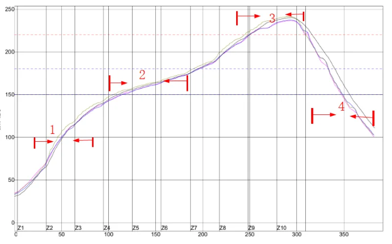
Reflow soldering involves heating solder paste to melt and form metallurgical bonds between components and PCB pads after stencil printing and placement. The process follows a thermal profile with distinct phases: preheat to activate flux and evaporate solvents, soak for even heat distribution, reflow to liquefy solder above its melting point, and cooling to solidify joints. For electrical engineers, precise control prevents thermal stress on components, especially moisture-sensitive devices classified per JEDEC J-STD-020E. Poor profiles lead to issues like delamination or warpage, impacting signal integrity and long-term reliability. Reflow oven types vary in heat transfer mechanisms, influencing delta T across the board, throughput, and energy use. Selecting the right method balances production speed with quality for diverse applications from consumer electronics to aerospace.
In PCB assembly lines, reflow soldering sets the pace for throughput, making efficiency critical. Engineers must consider board thickness, component density, and alloy type, such as lead-free SAC305 requiring higher peaks around 260 degrees C. Vapor phase systems limit maximum temperature to the fluid's boiling point, providing inherent overheat protection. Convection systems allow programmable profiles for flexibility. Both approaches demand thermocouple profiling to validate setups.
Principles of Convection Reflow Soldering
Convection reflow soldering relies on forced hot air circulation within a multi-zone oven to transfer heat uniformly to the assembly. Fans drive heated air over the PCB conveyor, ensuring consistent exposure across zones tailored to profile stages. Preheat zones ramp temperature gradually at 1 to 3 degrees C per second, minimizing shock. Soak zones hold steady for flux activation, followed by reflow zones peaking above liquidus for solder flow. Cooling zones then quench joints rapidly to refine microstructure.
This method excels in scalability, handling continuous high-volume runs with conveyor throughput up to hundreds of boards per hour. Airflow patterns, often turbulent or laminar, reduce shadows from tall components, improving heat penetration. Nitrogen atmospheres enhance joint quality by reducing oxidation. However, variations in board loading can cause delta T spreads exceeding 5 degrees C on thick or densely populated boards.
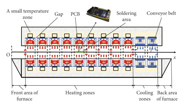
Engineers profile ovens using standards like IPC-7801 to monitor zone uniformity and conveyor speed. Adjustments via PID controls fine-tune ramps and peaks. Convection suits most SMT lines due to its versatility across board sizes.
Vapor Phase Reflow Soldering: Mechanism and Operation
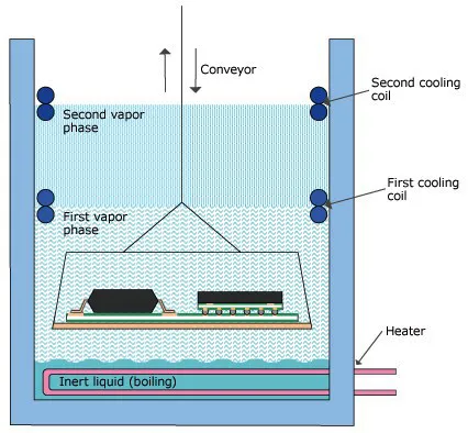
Vapor phase reflow soldering uses the saturated vapor of a high-boiling-point heat transfer fluid, generated by a sump heater, to envelop the PCB in a condensing thermal blanket. As clean vapor contacts the cooler assembly, latent heat of condensation delivers precise energy, achieving near-instant uniformity regardless of board topography. The process self-limits temperature to the fluid's boiling point, typically 200 to 260 degrees C, preventing overshoot. Assemblies lower vertically into the vapor chamber, reflow in minutes, then lift for cooling in ambient air.
This technique provides exceptional thermal stability, with delta T under 2 degrees C even on unevenly loaded or complex boards with cavities. Inert vapor excludes oxygen, minimizing dross and intermetallic growth. Short cycle times, around 3 to 5 minutes, suit prototyping or low-volume runs. Fluid purity maintenance via distillation ensures repeatability.
Vapor phase ovens occupy less floor space than inline convection systems, ideal for labs or flexible manufacturing. IPC-7530 guidelines apply for initial profiling, adapting to the unique heat transfer.
Reflow Oven Types: A Detailed Comparison
Reflow oven types primarily split into convection and vapor phase, each with distinct heat transfer physics shaping their application. Convection ovens feature linear tunnels with 8 to 12 zones for precise ramp control, supporting high throughput via mesh belts or edge chains. Vapor phase ovens operate batch-style, immersing boards in a static vapor cloud for simplicity. Hybrid systems exist but remain niche.
- Heat Transfer: Convection — Forced hot air circulation; Vapor Phase — Vapor condensation.
- Uniformity (Delta T): Convection — 3 to 10 degrees C typical; Vapor Phase — under 2 degrees C.
- Max Board Size: Convection — Large (up to 60 x 120 cm); Vapor Phase — Smaller (up to 30 x 40 cm).
- Throughput: Convection — High volume, continuous; Vapor Phase — Low to medium, batch.
- Atmosphere Control: Convection — Nitrogen optional; Vapor Phase — Inherently inert.
- Cost: Convection — Lower initial/operating; Vapor Phase — Higher due to fluid.
This reflow soldering comparison highlights trade-offs: convection prioritizes speed, vapor phase uniformity.
Reflow Soldering Advantages and Disadvantages
Convection reflow soldering advantages include cost-effectiveness, high productivity, and adaptability to varied profiles per IPC-7801. It handles large panels efficiently, integrating into automated lines with minimal downtime. Disadvantages involve airflow sensitivities causing hot spots, higher nitrogen needs for oxidation control, and potential shadowing under components.
Vapor phase reflow soldering advantages encompass superior uniformity, overheat prevention, and low voiding from gentle heating. It excels for high-reliability assemblies with fine-pitch BGAs or mixed technologies. Disadvantages include fluid costs, limited scalability, and slower cycles versus inline convection.
Engineers weigh these for prototypes versus production. Convection suits volume; vapor phase prototypes or dense boards.
Best Practices for Implementing Reflow Techniques
Validate thermal profiles with multi-point thermocouples placed at critical locations like corners and component centers, aligning to JEDEC J-STD-020E for MSL compliance. Preheat assemblies to remove moisture, avoiding popcorning. Optimize conveyor speed and zone setpoints iteratively for minimal overshoot. For convection, balance fan speeds to minimize turbulence-induced defects.
In vapor phase, maintain fluid level and purity through regular filtration, targeting 99.9% cleanliness. Use fiducials for precise immersion depth. Both methods benefit from nitrogen purging in preheat to enhance wetting.
Monitor solder paste via rheology tests pre-printing. Post-reflow, inspect per IPC-A-610 for joint acceptability.
Troubleshooting Reflow Soldering Challenges
Tombstoning often stems from rapid reflow ramps in convection; extend soak times for pad balance. Bridging in dense areas responds to finer stencils and lower paste volume. Voids, more prevalent in convection due to flux entrapment, reduce via extended preheat.
Vapor phase minimizes warpage from uniform stress but watch for fluid contamination causing residue. Profile deviations signal thermocouple faults or zone imbalances; recalibrate quarterly. X-ray analysis pinpoints subsurface issues early.
Conclusion
Convection and vapor phase reflow soldering each offer tailored solutions for PCB assembly demands, with convection driving efficiency and vapor phase ensuring precision. Electrical engineers benefit from matching reflow oven types to project specifics, leveraging reflow soldering advantages while mitigating disadvantages through profiling and standards. Implementing best practices yields robust joints, enhancing reliability. Future trends lean toward hybrid controls for versatility.
FAQs
Q1: What are the main reflow soldering advantages of convection over vapor phase?
A1: Convection reflow soldering provides higher throughput and lower costs, ideal for high-volume production. It supports larger boards and programmable profiles for diverse alloys. Vapor phase, while uniform, limits speed and scale. Per IPC-7801, convection excels in controlled zoning.
Q2: How does vapor phase reflow soldering improve uniformity compared to convection?
A2: Vapor phase uses condensation for a thermal blanket, achieving delta T under 2 degrees C across complex boards. Convection relies on air, prone to 5 to 10 degrees C variations. This reflow soldering advantage reduces stress on components.
Q3: What reflow soldering disadvantages should engineers consider for vapor phase?
A3: Higher equipment and fluid costs, plus batch processing, slow throughput versus continuous convection. Maintenance demands fluid distillation. Still, it shines for prototypes per JEDEC J-STD-020E compliance.
Q4: When to choose convection reflow soldering in PCB assembly?
A4: Opt for convection in scalable production with standard boards. It handles volume efficiently, minimizing reflow soldering disadvantages like cost when uniformity suffices via nitrogen.
References
IPC/JEDEC J-STD-020E — Moisture/Reflow Sensitivity Classification of Nonhermetic Surface Mount Devices. IPC/JEDEC, 2014
IPC-7801 — Reflow Oven Process Control Standard. IPC, 2015
IPC-7530 — Guidelines for Temperature Profiling for Solder Paste Reflow. IPC, 2007


