Introduction
Flexible and rigid-flex printed circuit boards represent a significant evolution in electronics design, enabling devices to adapt to compact, dynamic environments where traditional rigid boards fall short. These PCBs incorporate flexible substrates that allow bending, folding, or twisting without compromising electrical performance, making them ideal for applications demanding space savings and mechanical resilience. As consumer electronics, medical devices, and automotive systems grow more sophisticated, the demand for such interconnect solutions has surged. Engineers now prioritize flexible PCB applications in wearables, sensors, and high-density assemblies to meet miniaturization challenges. This article explores the technical foundations, design considerations, and manufacturing processes driving their adoption, with a focus on reliable performance in real-world conditions.
Understanding Flexible and Rigid-Flex PCBs
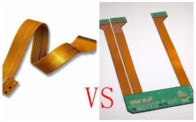
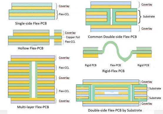
Flexible PCBs consist of circuits built on bendable substrates, typically layered with copper conductors, adhesives, and coverlays for protection. Rigid-flex PCBs combine rigid sections for component mounting with flexible areas for interconnection, providing structural support alongside adaptability. These designs eliminate the need for wiring harnesses, reducing assembly complexity and points of failure. In factory settings, distinguishing between static flex, used for occasional bends, and dynamic bending PCB configurations, subjected to repeated flexing, guides material and layout choices. Compliance with standards like IPC-6013 ensures qualification for performance in flexible printed boards. The hybrid nature of rigid-flex boards supports complex geometries unattainable with purely rigid or flexible variants.
Key Materials: The Role of Polyimide PCB Substrate
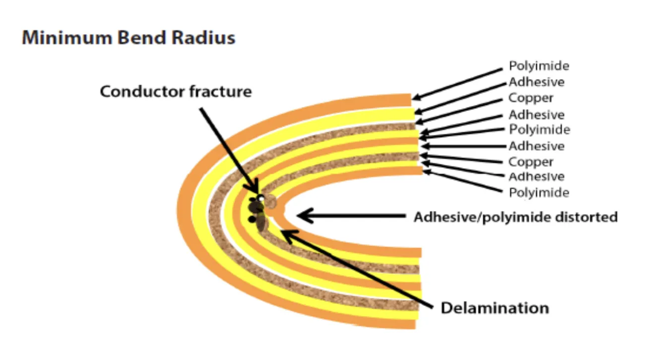
Polyimide serves as the cornerstone substrate in most flexible PCBs due to its exceptional thermal stability, tensile strength, and chemical resistance. This material withstands temperatures exceeding 200 degrees Celsius during soldering and maintains integrity under mechanical stress, outperforming alternatives like polyester in demanding environments. Factory processes laminate copper foil onto polyimide films, often using adhesiveless bonding for enhanced peel strength in dynamic applications. Coverlay films, also polyimide-based, protect traces while allowing precise laser routing for bend areas. Selection of polyimide thickness, typically 25 to 125 micrometers, balances flexibility with durability. Adherence to material specifications prevents issues like cracking during repeated cycles.
Flexible PCB Design Guidelines for Reliability
Effective flexible PCB design guidelines emphasize trace routing perpendicular to bend lines to minimize stress concentrations. Engineers should incorporate generous bend radii, at least 10 times the total stack-up thickness for dynamic bending PCB use, to avoid copper fatigue. Vias and pads in flex zones require teardrop shapes and reinforcement to distribute forces evenly. Stiffeners added to rigid-flex transitions enhance component mounting stability without restricting flex areas. Factory-driven insights recommend simulating strain via finite element analysis during layout. Following IPC-2223 sectional design standards optimizes these elements for long-term reliability.
Designers must also consider layer stack-up, positioning power and ground planes away from flex zones to reduce impedance variations. Solder mask openings demand precise control to prevent bridging during assembly. Testing protocols verify adhesion strength post-flexing, ensuring no delamination occurs.
Rigid-Flex PCB Manufacturing Process
The rigid-flex PCB manufacturing process begins with material preparation, where polyimide flex cores are laminated with rigid FR-4 sections using epoxy prepregs. Sequential lamination builds the stack-up, isolating flex areas with controlled adhesive flow to prevent resin bleed. Photolithography patterns copper on both rigid and flex regions, followed by via drilling and plating tailored to hybrid structures. Factory alignment during pressing maintains registration across sections, critical for multilayer builds. Coverlay application and outline routing complete the flex tails, with flying leads options for connectors.
Post-processing includes electrical testing and bend conditioning to simulate service life. Quality checks per IPC standards confirm dimensional stability and continuity. This integrated approach yields boards ready for automated assembly.
Handling Dynamic Bending in PCB Applications
Dynamic bending PCB configurations excel in applications like robotic arms, foldable displays, and medical endoscopes, where circuits endure millions of cycles. Material fatigue becomes a primary concern, necessitating copper ductility enhancements through annealing. Flex endurance testing cycles boards at specified radii and angles, correlating results to field performance. Integration in automotive sensors demands vibration resistance alongside flex capability. Flexible PCB applications extend to aerospace harness replacements, slashing weight by up to 70 percent compared to wired equivalents. Engineers balance cycle life with signal integrity by optimizing trace widths and spacings.
Best Practices for Implementation
Start with thorough stack-up planning, defining rigid-flex boundaries early to streamline procurement. Collaborate with manufacturers on panelization strategies that accommodate flex tail variations. Implement design for manufacturability by avoiding acute angles in flex zones and specifying roll-to-roll processing for high-volume polyimide substrates. Post-assembly, environmental conditioning per J-STD-020 verifies moisture sensitivity. Regular audits of incoming materials ensure polyimide consistency. These steps align production with end-use demands.
Flexible PCB Applications Across Industries
In consumer electronics, flexible PCBs enable slim wearables and curved screens, routing signals through hinges without failure. Medical devices leverage their biocompatibility for implants and catheters, where miniaturization aids minimally invasive procedures. Automotive ADAS systems use rigid-flex boards for camera modules in tight engine bays, enduring thermal cycling. Aerospace benefits from lightweight interconnects in satellites, resisting launch vibrations. Industrial robotics employs dynamic bending PCB for joint articulations, enhancing motion range.
Conclusion
Flexible and rigid-flex PCBs have transformed electronics by bridging rigidity and adaptability, powering innovations in compact, mobile designs. Key to their success lies in polyimide substrates, precise design guidelines, and robust manufacturing processes. Engineers adopting these principles achieve superior reliability in dynamic environments. As demands for smaller, tougher devices intensify, these boards will remain central. Prioritizing standards ensures consistent factory outcomes and field performance.
FAQs
Q1: What are the essential flexible PCB design guidelines for dynamic applications?
A1: Flexible PCB design guidelines stress minimum bend radii of 10 times stack-up thickness, trace routing perpendicular to flex lines, and reinforced vias. Polyimide substrates enhance cycle life, while simulations predict strain. Factory testing verifies endurance, aligning with IPC-2223 for optimal layouts. These practices prevent fatigue in repeated bending scenarios.
Q2: How does the rigid-flex PCB manufacturing process differ from standard rigid boards?
A2: The rigid-flex PCB manufacturing process involves sequential lamination of flex cores with rigid sections, precise adhesive control, and isolated flex routing. Polyimide layers bond without bleed, followed by hybrid plating. This yields integrated structures versus separate panels in rigid production. Standards like IPC-6013 guide qualification for performance.
Q3: What role does polyimide play as a PCB substrate in flexible applications?
A3: Polyimide PCB substrate offers high thermal resistance and flexibility, ideal for flexible PCB applications under stress. It supports adhesiveless lamination for peel strength in dynamic bending PCB use. Thickness selection tunes bendability, ensuring reliability in medical and automotive contexts. Factory specs maintain uniformity for consistent results.
Q4: Why choose dynamic bending PCB for robotics and wearables?
A4: Dynamic bending PCB suits robotics and wearables by withstanding millions of flex cycles without signal loss. Design guidelines incorporate ductile copper and stiffeners for stability. Applications benefit from weight reduction and space efficiency. Manufacturing per standards ensures longevity in motion-intensive roles.
References
IPC-2223E — Sectional Design Standard for Flexible/Rigid-Flexible Printed Boards. IPC
IPC-6013DS — Qualification and Performance Specification for Flexible and Rigid-Flex Printed Boards. IPC
J-STD-020E — Moisture/Reflow Sensitivity Classification of Nonhermetic Surface Mount Devices. JEDEC


