Introduction
High-power applications such as power supplies, LED lighting systems, and automotive electronics demand robust thermal management to ensure reliability and longevity. Choosing between aluminum PCBs and FR-4 PCBs involves balancing performance needs with budget constraints. Aluminum PCBs excel in heat dissipation, making them ideal for scenarios where component temperatures exceed standard limits. FR-4 PCBs, however, offer versatility and lower costs for less demanding designs. This article provides a detailed aluminum PCB vs FR4 cost comparison, focusing on fabrication expenses, material differences, and strategies for PCB cost optimization. Factory insights reveal that informed material selection can reduce overall project expenses without compromising quality.
Understanding Aluminum PCBs vs FR-4 PCBs
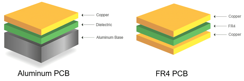
Aluminum PCBs, also known as metal core printed circuit boards, consist of an aluminum base layer, a thin dielectric layer, and copper traces. The aluminum core provides superior mechanical strength and thermal conductivity compared to traditional substrates. FR-4 PCBs use woven glass fabric impregnated with epoxy resin, forming a rigid, electrically insulating board that supports multilayer constructions. While FR-4 dominates general-purpose electronics due to its processability, aluminum PCBs target applications requiring efficient heat spreading. Both types adhere to qualification standards like IPC-6012E for rigid printed boards, ensuring consistent performance across production runs. Factory-driven evaluations highlight how substrate choice influences not just thermal behavior but also long-term assembly yields.
Thermal Performance in High-Power Applications
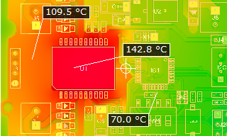
In high-power circuits, excessive heat from components like MOSFETs or IGBTs can lead to thermal runaway, reducing mean time between failures. Aluminum PCBs achieve thermal conductivities of 1 to 2 W/m·K through the dielectric layer, far surpassing FR-4's approximately 0.25 W/m·K. This difference allows aluminum designs to maintain junction temperatures 20 to 50 percent lower under identical power loads. FR-4 relies on copper planes and vias for heat transfer, which becomes inefficient beyond moderate densities. For applications exceeding 50 W per square inch, aluminum prevents hotspots that degrade solder joints over time. Engineers must model thermal profiles early to justify the premium, aligning with design guidelines in IPC-2221.
Material Cost Breakdown
Material expenses form the foundation of aluminum PCB fabrication cost and FR-4 PCB cost. Aluminum substrates cost more due to the metal core's raw material and bonding processes, typically ranging from $0.08 to $0.15 per square inch for standard thicknesses. FR-4 laminates, by contrast, fall between $0.02 and $0.05 per square inch, benefiting from abundant supply chains and simpler production. Dielectric layers in aluminum PCBs require thermally conductive fillers, adding to the premium. Copper foil thickness, often 1 to 3 oz in both, impacts costs similarly, but aluminum demands specialized foils for adhesion. Volume orders amplify these differences, with FR-4 scaling more favorably for prototypes under 100 units.
Suggested Reading: Aluminum vs FR4 PCB Material Which One is Better for Your Design?
Fabrication Process and Cost Factors
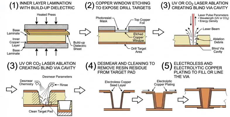
Fabrication introduces variances in aluminum PCB cost per square inch versus FR-4. Aluminum PCBs are predominantly single or double-sided, limiting multilayer complexity and requiring precise controlled-depth drilling for vias. FR-4 supports up to 20+ layers with standard sequential lamination, spreading setup costs over more panels. Routing aluminum demands carbide tools to avoid base exposure, increasing tooling expenses by 20 to 50 percent. Solder mask and silkscreen application follows similar steps, but aluminum's flatness tolerances per IPC-A-600 demand extra fixturing. Panel utilization suffers in aluminum due to larger minimum feature sizes, elevating per-unit costs for small runs. Engineers optimize by maximizing panel yield through efficient nesting.
- Base Material — Aluminum PCB: Higher (metal core); FR-4 PCB: Lower (epoxy glass); Impact: 30–50% premium for aluminum
- Layer Count Capability — Aluminum PCB: 1–2 typical; FR-4 PCB: Multi-layer standard; Impact: FR-4 lower for complex designs
- Drilling/Routing — Aluminum PCB: Specialized tools; FR-4 PCB: Standard; Impact: +20–40% for aluminum
- Thermal Vias — Aluminum PCB: Limited; FR-4 PCB: Extensive possible; Impact: Aluminum relies on core
- Minimum Order Quantity — Aluminum PCB: Higher setup; FR-4 PCB: Flexible; Impact: Economies favor FR-4 volume
Aluminum PCB vs FR-4: Side-by-Side Cost & Performance Table
| Feature | Aluminum PCB | FR-4 PCB | Winner / Impact |
|---|---|---|---|
| Thermal Conductivity | 1–2 W/m·K (through dielectric) | ~0.25–0.3 W/m·K | Aluminum – superior heat spreading |
| Layer Count | Typically 1–2 layers | Up to 20+ layers | FR-4 for complex routing |
| Material Cost/sq in | $0.08–$0.15+ (base) | $0.02–$0.05 (base) | FR-4 lower |
| Fabrication Premium | Higher (special tools, limited layers) | Lower (standard processes) | FR-4 for prototypes/multilayer |
| Best Power Density | >10–50 W/sq in or higher | Moderate (< moderate densities) | Aluminum for high-power |
| Mechanical Strength | Excellent rigidity | Good but less robust | Aluminum |
| Typical Prototype Cost (10x10 in panel) | $80–$200+ | $20–$50 | FR-4 cheaper upfront |
| Volume Scaling (1k+ units) | 1.5–2.5x FR-4 | Baseline | Aluminum narrows gap |
Direct Cost Comparison for High-Power Designs
Aluminum PCB vs FR4 cost comparison reveals aluminum at 2 to 4 times the price for equivalent footprints in high-power setups. For a 10x10 inch prototype panel, FR-4 PCB cost might total $20 to $50, while aluminum PCB fabrication cost reaches $80 to $200. Engineers often start with our pros and cons of aluminum PCBs before finalizing high-power layouts. Production volumes shift this ratio; at 1,000 units, aluminum drops to 1.5 to 2.5 times due to amortized tooling. High-power needs like 2 oz copper or impedance control add proportionally more to FR-4 in multilayers. Factory data shows aluminum's edge in total cost of ownership for heat-intensive apps, avoiding rework from thermal failures. Procurement teams track these via spreadsheets, factoring lead times of 2–4 weeks for aluminum versus 1–2 for FR-4.
Total Cost of Ownership & Real-World Case Studies
Upfront fabrication is only part of the story. Total cost of ownership (TCO) often favors aluminum in heat-intensive applications by reducing external cooling components, lowering failure rates, and cutting maintenance/rework.
Case example (LED lighting): Streetlight arrays using aluminum PCBs achieved better thermal performance, extended LED lifespan, and reduced the need for bulky heatsinks—offsetting higher board cost through lower system-level expenses and fewer replacements.
Power supply example: Designs switching to aluminum for high-density sections avoided thermal runaway issues seen in FR-4 prototypes, improving reliability and avoiding costly field failures.
When power dissipation exceeds FR-4’s practical limits, aluminum’s reliability edge frequently delivers long-term savings despite the initial premium.
PCB Cost Optimization Strategies
PCB cost optimization starts with application-specific selection: reserve aluminum for densities over 10 W/sq cm where FR-4 vias fail. Hybrid designs embed aluminum inserts in FR-4 for targeted dissipation, blending costs effectively. Reduce layers by leveraging aluminum's single-side sufficiency, cutting lamination cycles. Specify standard thicknesses like 1.6 mm to avoid custom surcharges. Panel sharing among designs boosts yield, particularly for aluminum's rigidity constraints. Simulate thermal loads per J-STD-020 to validate choices, preventing over-specification. These practices, rooted in factory workflows, yield 15 to 30 percent savings without performance trade-offs.
Manufacturing Process Deep Dive & DFM Tips
Beyond basic fabrication, aluminum requires attention to CTE (coefficient of thermal expansion) mismatch to minimize warpage during reflow. Via-in-pad options are more restricted, and routing must avoid exposing the base metal.
Practical DFM tips:
- Keep minimum feature sizes generous on aluminum.
- Use thermal vias sparingly (the core handles most spreading).
- Prototype critical sections in FR-4 with enhanced vias first when possible.
- Collaborate early with manufacturers on stackup and tolerances.
Following these guidelines streamlines production and improves yields.
Best Practices for High-Power PCB Selection
Adopt a stepwise evaluation: quantify power dissipation via Joule heating models first. Prototype FR-4 with thermal vias for validation before committing to aluminum. Ensure compliance with IPC-6012E during qualification to minimize yield losses. Collaborate with fabrication partners on DFM reviews, focusing on via-in-pad restrictions for aluminum. Monitor CTE mismatch between layers to avert warpage in reflow. Long-term, track field failure rates to refine future budgets. These factory-aligned steps ensure cost-effective, reliable high-power boards.
2026 Pricing Trends & Future-Proofing
As of 2026, raw material inflation (particularly copper foil and laminates) has created segmented pricing: standard FR-4 remains relatively stable for commodity boards, while specialized materials like aluminum cores reflect ongoing supply pressures. Aluminum pricing benefits from volume but stays sensitive to metal market fluctuations.
Future-proofing tips:
- Design modularly to allow material swaps.
- Build in thermal headroom for evolving component power levels.
- Consider hybrid constructions for flexibility.
- Partner with fabricators offering transparent 2026 quoting to lock in competitive rates.
Staying informed on these trends helps balance today's costs with tomorrow's performance needs.
Conclusion
Aluminum PCBs command higher costs due to materials and processes but deliver unmatched thermal performance for high-power demands. FR-4 remains economical for versatile, lower-heat applications. Thorough aluminum PCB vs FR4 cost comparison guides optimal choices, emphasizing volume, complexity, and lifecycle savings. PCB cost optimization hinges on precise thermal modeling and standards adherence. Engineers achieve balanced designs by weighing upfront fabrication against operational reliability. Prioritizing these factors elevates project success in demanding environments.
FAQs
Q1: What factors drive aluminum PCB cost per square inch?
A1: Aluminum PCB cost per square inch depends on base thickness, copper weight, and thermal dielectric quality, typically ranging higher than FR-4 due to metal core premiums. Fabrication adds from specialized routing and bonding. For high-power apps, 1–2 W/m·K conductivity justifies the expense. Volume production lowers it via panel efficiency. Factory standards ensure quality without excess.
Q2: How does FR-4 PCB cost compare to aluminum for prototypes?
A2: FR-4 PCB cost stays low at $0.02–$0.10 per square inch for prototypes, versus $0.08–$0.15 for aluminum, owing to simpler materials and processes. Multilayer FR-4 scales well for complex signals. Aluminum suits thermal-critical singlesides. Optimize by nesting designs. Quick turns favor FR-4 availability.
Q3: What is the best approach for aluminum PCB vs FR4 cost comparison in power electronics?
A3: Aluminum PCB vs FR4 cost comparison favors aluminum when heat exceeds FR-4 limits, despite 2–4x fabrication premium. Calculate total ownership including failure risks. Use simulations for thresholds. Hybrids blend benefits. Standards like IPC-6012E guide qualification. Volume shifts economics toward parity.
Q4: How can engineers achieve PCB cost optimization in high-power designs?
A4: PCB cost optimization involves thermal profiling to select substrates wisely, maximizing panel utilization, and standard specs. Avoid unnecessary layers on aluminum. Prototype FR-4 first. DFM reviews cut iterations. Lifecycle analysis reveals aluminum's value in reliability. Factory insights prioritize yield.
References
IPC-6012E — Qualification and Performance Specification for Rigid Printed Boards. IPC, 2017
IPC-2221B — Generic Standard on Printed Board Design. IPC, 2012
IPC-A-600K — Acceptability of Printed Boards. IPC, 2020
J-STD-020E — Moisture/Reflow Sensitivity Classification of Nonhermetic Surface Mount Devices. JEDEC, 2014