Introduction
Electronic hobbyists often dive into building circuits with enthusiasm, but unexpected failures can dampen the excitement. Simple circuit tests provide a straightforward way to identify issues early, saving time and components. DFT basics revolve around incorporating test-friendly features during design and using basic tools for verification. This guide focuses on hobbyist testing methods, including continuity testing and basic component testing, to make your projects more reliable. By mastering these techniques, you can troubleshoot effectively without advanced equipment. Whether prototyping on a breadboard or soldering a custom PCB, these DFT basics empower confident builds.
What Is DFT and Why It Matters for Hobbyists
Design for Testability, or DFT, refers to strategies that make circuits easier to check for faults during and after assembly. For hobbyists, DFT basics mean adding accessible points for probes and planning routine checks like continuity testing. This approach prevents small errors from becoming big problems in complex projects. Industry standards such as IPC-2221 emphasize test points and clear routing to support reliable verification. Without DFT considerations, diagnosing opens or shorts becomes guesswork, leading to wasted effort. Embracing these principles early enhances project success and builds troubleshooting skills.
In hobbyist projects, DFT matters because resources are limited compared to professional setups. Simple circuit tests catch assembly mistakes, like poor solder joints, before powering up. They also verify component functionality, reducing the risk of damaging sensitive parts. For instance, continuity testing confirms traces connect properly, a core DFT basic. This proactive testing aligns with best practices in electronic assembly, ensuring circuits perform as intended. Ultimately, it turns hobbyist testing into a rewarding part of the creative process.
Core Principles of Simple Circuit Testing
At its heart, simple circuit tests rely on measuring electrical properties to detect faults. Continuity testing checks for unbroken paths by detecting low resistance between points. Basic component testing evaluates individual parts like resistors or diodes using voltage, resistance, or current readings. These methods stem from fundamental electronics, where good connections show predictable behaviors. DFT basics encourage spacing components for easy probe access during these checks. Understanding these principles allows hobbyists to apply them systematically.
Power-off testing forms the foundation, starting with visual inspection for obvious issues like bridges or lifts. Then, resistance measurements reveal opens or shorts in traces. For powered tests, monitor voltages at key nodes to confirm expected levels. Capacitors require checking for shorts or open circuits via discharge times. These steps build on each other, providing layered assurance. Adhering to standards like J-STD-001 for soldering helps ensure test results reflect true performance.
Continuity Testing: The First Line of Defense
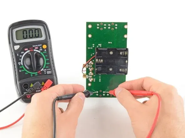
Continuity testing stands as a cornerstone of hobbyist testing, verifying that current can flow without excessive resistance. Use a multimeter in continuity mode, which beeps for paths under a few ohms. Probe each end of traces, pads, and vias on your unpowered board. Absence of tone indicates an open, often from lifted pads or broken wires. Always test from power to ground and between signals to map the netlist mentally. This DFT basic catches 80 percent of assembly faults quickly.
Deeper continuity checks extend to vias and under components by gently probing solder joints. Clean flux residue first, as it can mimic shorts. Compare readings across similar nets for consistency. In multilayer boards, focus on high-current paths prone to defects. Pair this with visual checks per IPC-A-610 criteria for joint appearance. Regular practice turns this into an intuitive skill for any project.
For complex circuits, create a test plan listing nets to verify. Start at inputs and work outward, noting any anomalies. False positives arise from probe slip or battery probes touching capacitors. Discharge boards fully before testing to avoid misleading capacitance effects. This methodical approach embodies DFT basics, streamlining hobbyist testing workflows.
Basic Component Testing Techniques
Basic component testing isolates parts to confirm they meet specs before integration. Resistors measure direct resistance; values far off signal damage from heat or static. Diodes show low forward voltage drop and high reverse resistance. Transistors test via base-emitter junctions behaving like diodes. Capacitors check for shorts in resistance mode and charge curves in capacitance mode. These tests prevent cascading failures in circuits.
LEDs light up under forward bias, confirming functionality without values. Inductors resemble resistors at DC but verify coils visually for breaks. Integrated circuits test power pins for shorts and basic logic response if accessible. Always reference datasheets for pinouts, though hobbyists memorize common ones. Power tests at low voltage reveal heat or smoke risks early. Integrating these into DFT basics ensures robust assemblies.

Remove components for accurate in-circuit reads, as parallels skew results. Use the highest range initially to avoid damaging sensitive parts. For electrolytics, polarity matters; reverse can cause explosions. Potentiometers sweep full resistance smoothly. Relays click and show coil continuity plus contact closure. These steps form practical hobbyist testing routines.
Practical Best Practices for Hobbyist DFT
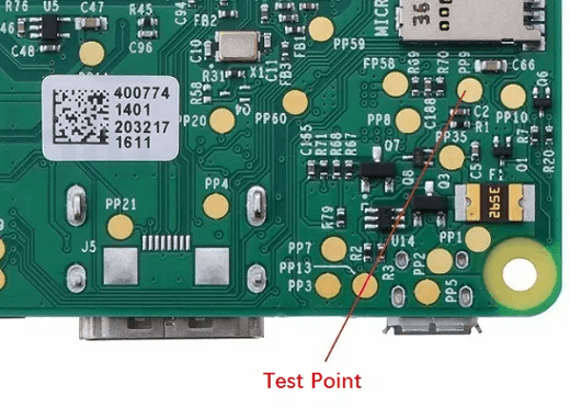
Start DFT in design by adding 0.5mm test pads on every net, spaced for probe tips. Route traces wider at test points for durability. Use through-hole for critical signals if surface-mount crowds them. Breadboard prototypes first to validate logic before PCB commitment. Label silkscreen clearly for probe guidance. These features make simple circuit tests effortless.
Assembly follows with clean soldering, avoiding cold joints that fail continuity. Inspect under magnification for bridges. Fixture boards if possible, using foam for bed-of-nails simulations. Power up gradually, measuring supplies first. Log voltages at stages for comparison. Standards like IPC-TM-650 outline methods adaptable to home setups.
Safety ranks paramount: discharge capacitors, use insulated probes, limit voltages. Isolate sections with jumpers for sectional testing. Software tools simulate tests pre-build if available. Document fixtures and readings for iterations. Common pitfalls include probing live high voltage or ignoring ground loops. Consistent habits elevate hobbyist testing precision.
Troubleshooting Common Circuit Faults
Faulty power rails top the list, showing no voltage or ripples. Check regulators and decoupling caps first via basic component testing. Intermittent issues point to cold joints; reflow and retest continuity. Noisy signals suggest ground problems; verify star grounding. Oscillating circuits fail oscillation tests; probe feedback loops carefully.
Component substitution isolates culprits: swap suspects and retest. Thermal faults appear under load; monitor with finger or thermometer safely. Firmware bugs mimic hardware; toggle pins manually. Multi-stage faults require divide-and-conquer: halve the circuit repeatedly. Persistence pays off, turning puzzles into learning.
Case in point: a blinking LED driver fails continuity on traces but passes component checks. Recheck vias, often drilled poorly. Another: amplifier hums from power supply noise, fixed by better decoupling per J-STD-001 guidelines. These scenarios highlight DFT basics in action.
Conclusion
Mastering DFT basics transforms hobbyist projects from trial-and-error to efficient builds. Continuity testing and basic component testing form the toolkit essentials. Incorporate test points and methodical checks for reliability. Reference standards ensure professional-grade results at home. Practice builds confidence, reducing debug time dramatically. Start simple, scale up, and enjoy reliable circuits every time.
FAQs
Q1: What are DFT basics for simple circuit tests?
A1: DFT basics involve designing circuits with accessible test points and using tools like multimeters for verification. Hobbyists focus on power-off checks first, such as measuring resistances and voltages. This prevents faults from propagating. Plan nets during layout for quick probing. These practices align with assembly standards for dependable outcomes.
Q2: How does continuity testing work in hobbyist testing?
A2: Continuity testing uses a multimeter to beep on low-resistance paths, confirming trace and joint integrity. Probe pairs systematically on unpowered boards. Clean surfaces avoid false readings. It catches opens and shorts early in DFT basics. Extend to vias by careful access. Essential for every build verification.
Q3: What is basic component testing for beginners?
A3: Basic component testing measures resistors for value, diodes for bias direction, and capacitors for shorts. Use multimeter modes matching the part. Remove from circuit for accuracy in hobbyist testing. Check transistors as paired diodes. Prevents integration of bad parts. Builds foundational skills quickly.
Q4: Why include test points in simple circuit tests?
A4: Test points enable probe access without desoldering, core to DFT basics. Place on all nets, especially power and signals. They facilitate continuity testing and voltage checks. Improves troubleshooting speed for hobbyists. Follow design guidelines for spacing. Enhances overall project reliability.
References
IPC-2221B — Generic Standard on Printed Board Design. IPC, 2012
J-STD-001H — Requirements for Soldered Electrical and Electronic Assemblies. IPC, 2018
IPC-A-610J — Acceptability of Electronic Assemblies. IPC, 2020
IPC-TM-650 — Test Methods Manual. IPC, latest revision


