Introduction
Modern electronics increasingly require interconnect solutions that conform to tight spaces and dynamic movements, driving the adoption of flexible PCBs. These flexible circuits enable innovations in wearables, medical devices, and automotive systems by allowing bending and folding without compromising electrical performance. While IPC-6012 sets qualification and performance benchmarks for rigid printed boards, its principles influence the development of standards for flexible variants, ensuring reliability across applications. Factory-driven manufacturing processes must align with PCB standards to deliver consistent quality in flex PCB design and production. This article explores how these standards address the unique challenges of flexible circuits in PCB manufacturing. Engineers benefit from understanding these alignments to optimize designs for real-world demands.

Understanding IPC-6012 and Its Relevance to Flexible PCBs
IPC-6012 establishes qualification and performance specifications for rigid printed boards, defining classes based on end-use reliability needs, such as Class 2 for general electronics and Class 3 for high-reliability applications. It covers requirements for materials, plating, dimensions, and environmental testing to ensure boards withstand thermal cycling and mechanical stress. Although primarily for rigid boards, IPC-6012 provides a foundational framework that informs flexible PCB manufacturing, particularly in rigid-flex hybrids where rigid sections must meet these criteria. Flexible circuits, governed by related PCB standards, adapt these principles to handle repeated flexing without failure. Manufacturers reference such standards to qualify processes, verifying conductor integrity and insulation resistance post-fabrication. This cross-application insight helps electric engineers select appropriate specifications during flex PCB design.
In factory settings, adherence to IPC-6012-like performance metrics ensures that even flexible assemblies maintain signal integrity under vibration. The standard's emphasis on solderability and hole wall quality translates to flex processes, where plating uniformity prevents cracks during bending.
Key Differences and Adaptations for Flexible Circuits
Flexible PCBs differ fundamentally from rigid ones due to their substrate materials, like polyimide, which offer high thermal stability and ductility compared to FR-4. IPC standards for flexible circuits extend rigid board qualifications by adding flex-specific tests, such as cyclic bending endurance to simulate operational stresses. While IPC-6012 focuses on flatness and warpage control for rigid boards, flexible variants prioritize minimum bend radius to avoid trace fractures. PCB manufacturing for flex involves specialized lamination to bond copper foils without voids, ensuring dielectric strength. Engineers must consider these adaptations in flex PCB design to balance flexibility with electrical performance. Factory insights reveal that improper material selection leads to delamination, underscoring the need for standard-compliant qualification.
Rigid-flex combinations leverage IPC-6012 for stiffeners while applying flex rules to dynamic areas, creating seamless transitions. This hybrid approach meets demands in aerospace where weight savings and reliability converge.
Technical Principles in Flex PCB Design and Manufacturing
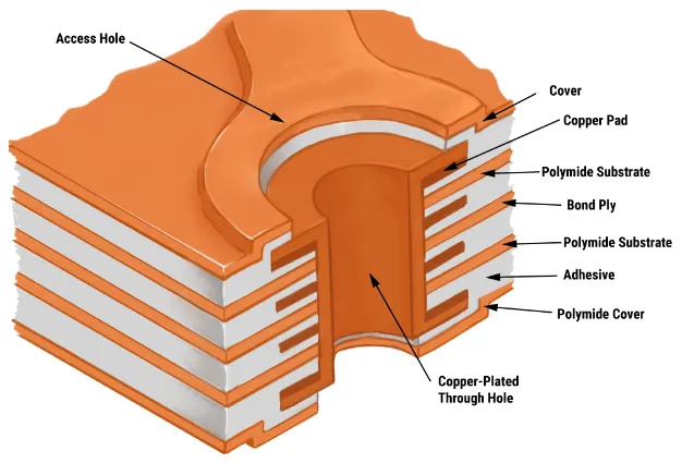
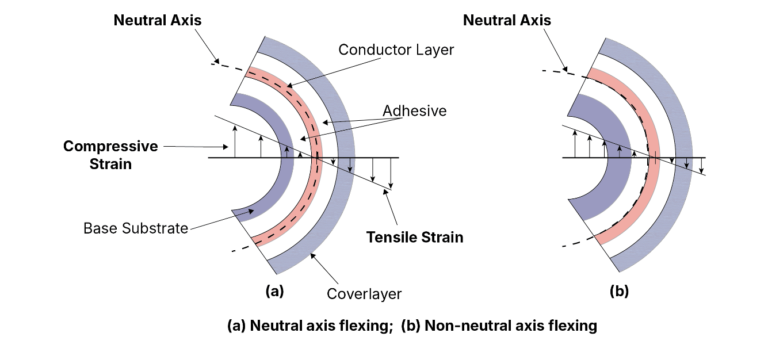
Flex PCB design begins with defining the bend zones, where traces follow curved paths to distribute strain evenly and prevent fatigue. Standards dictate trace width and spacing adjustments in flex areas, wider than rigid to accommodate elongation during flexing. Coverlay films protect conductors, similar to solder masks on rigid boards, but with flexibility to avoid cracking. In PCB manufacturing, adhesive-based or adhesiveless constructions influence yield; adhesiveless lamination reduces outgassing risks during high-temperature processes. Electric engineers optimize stack-ups by simulating strain distribution, ensuring vias in transition zones withstand shear forces. These principles align with PCB standards to guarantee long-term reliability in dynamic environments.
Material qualification tests, drawn from performance specs, evaluate peel strength and dielectric breakdown under humidity. Factories implement controlled rolling and etching to maintain copper ductility, critical for flexible circuits.
Multilayer flex adds complexity with interlayer alignment, requiring precise registration to avoid shorts. Manufacturing sequences prioritize flex tails last to minimize handling damage.
Best Practices for Meeting PCB Standards in Production
To comply with relevant PCB standards, start with design for manufacturability (DFM) reviews, focusing on bend allowances and stiffener placement. Select copper weights suited to flex cycles; lighter foils enhance bendability but demand finer plating control. In PCB manufacturing, use plasma etching for clean coverlay edges, reducing contamination risks. Qualification involves thermal shock and flex endurance testing per class requirements, verifying no opens or intermittents after thousands of cycles. Engineers should specify class levels early, as Class 3 demands tighter tolerances on hole geometries and surface finish. Factory-driven process controls, like automated optical inspection (AOI), catch defects early, aligning with acceptability criteria.
For rigid-flex, separate rigid and flex fabrications before lamination, ensuring IPC-6012 compliance in rigid zones. Iterative prototyping refines designs, incorporating feedback from strain gauge tests.
Solder mask alternatives like coverlay require specific cure profiles to prevent bubbling. Documentation of material lots traces compliance throughout the supply chain.
Quality Control and Troubleshooting in Flexible PCB Manufacturing
Quality control in flexible circuits emphasizes visual and dimensional checks adapted from general PCB standards, such as IPC-A-600 for acceptability. Common issues like coverlay lifts stem from poor adhesion, resolved by surface activation pre-lamination. Warpage in rigid-flex arises from CTE mismatches; controlled cooling mitigates this. Electrical testing post-flexing confirms continuity, with flying probe systems ideal for odd shapes. Factories log test data to qualify lots, supporting customer audits. Troubleshooting involves cross-section analysis to diagnose plating voids, ensuring root cause correction.
Environmental conditioning precedes performance verification, simulating assembly reflow. This proactive approach minimizes field failures in demanding applications.
Conclusion
Flexible PCBs meet modern electronics demands through rigorous adherence to evolving PCB standards, building on IPC-6012 foundations for rigid reliability while incorporating flex-specific qualifications. Factory insights highlight the interplay of design, materials, and processes in achieving durable flexible circuits. Electric engineers gain from structured approaches to flex PCB design and manufacturing, ensuring performance in compact, mobile devices. Prioritizing these standards reduces risks and enhances product lifecycles. As applications expand, staying aligned with updates maintains competitive edges in quality.
FAQs
Q1: What is an IPC-6012 flexible PCB, and how does it differ from standard rigid boards?
A1: An IPC-6012 flexible PCB refers to flexible or rigid-flex designs where rigid sections comply with IPC-6012 performance specs, while flex areas follow complementary standards. Unlike rigid boards, flexible circuits use ductile substrates for bending, requiring additional tests like cyclic flexing. This hybrid ensures reliability in dynamic uses, with factory processes adapting plating and lamination for strain resistance.
Q2: How do PCB standards guide flex PCB design for electric engineers?
A2: PCB standards outline bend radii, trace routing, and material specs to prevent fatigue in flexible circuits. Engineers apply these in layout tools, curving traces in flex zones and adding fillets at bends. Compliance verifies via simulations and prototypes, optimizing for manufacturing yields. Factory alignment reduces defects like cracks.
Q3: What role does IPC play in flexible circuits manufacturing?
A3: IPC standards like those for qualification dictate tests for thermal stability and electrical integrity in PCB manufacturing of flexible circuits. They classify boards by reliability, influencing process controls such as etching and coverlay application. Manufacturers qualify equipment to meet these, ensuring consistent output for high-volume production.
Q4: Why are standards critical in PCB manufacturing for modern flexible applications?
A4: Standards provide verifiable criteria for materials and processes, essential for flexible circuits in medical and automotive uses. They address unique challenges like delamination, standardizing inspections and tests. This factory-driven compliance boosts yield and reliability, meeting engineer specs without custom iterations.
References
IPC-6012E — Qualification and Performance Specification for Rigid Printed Boards. IPC, 2020
IPC-6013E — Qualification and Performance Specification for Flexible/Rigid-Flexible Printed Boards. IPC, 2021
IPC-A-600K — Acceptability of Printed Boards. IPC, 2020


