Introduction
In critical applications such as aerospace, printed circuit boards must endure extreme conditions including vibration, thermal cycling, and high altitudes. Engineers designing PCBs for these environments face choices between commercial high-reliability standards like IPC Class 3 and military specifications such as MIL-Spec. IPC Class 3 PCBs meet demanding performance needs for continuous operation, while MIL-Spec PCBs incorporate additional safeguards for defense systems. Understanding the differences ensures selection of the appropriate specification to avoid failures in flight-critical systems. This article compares IPC Class 3 and MIL-Spec requirements, focusing on design, manufacturing, and qualification aspects relevant to high-reliability PCBs.
Understanding IPC Class 3 PCBs
IPC Class 3 defines the highest level of quality for commercial electronics requiring uninterrupted performance. These PCBs serve applications where downtime poses significant risks, such as avionics and industrial controls. Under IPC-6012 for rigid boards and IPC-6013 for flexible and rigid-flex boards, Class 3 imposes strict criteria on fabrication and inspection. No lifted or fractured annular rings are permitted, and plating voids in vias or holes must be absent. Minimum internal annular ring measures one mil from the drilled hole edge, while external annular ring requires two mils minimum. Factory processes emphasize controlled impedance testing via coupons that replicate circuit patterns.
Cleanliness requirements prevent ionic residues from compromising reliability over time. Solder mask coverage must achieve full adhesion with thicknesses between 15 and 35 microns. Materials selection prioritizes high glass transition temperature above 170 degrees Celsius to resist delamination during thermal stress. Vias demand at least one mil of copper plating thickness, with no exceptions for barrel fill below 75 percent in through-holes. These standards align production with zero tolerance for functional defects, making IPC Class 3 PCBs suitable for many aerospace subsystems.
MIL Spec PCB: Requirements for Critical Applications
MIL-Spec PCBs adhere to military performance specifications tailored for defense and aerospace platforms. MIL-PRF-31032 establishes requirements for printed wiring boards, encompassing rigid, flexible, and high-frequency types. This specification baselines design on IPC Class 3 performance but adds layers of oversight and testing. Qualification involves a technical review board, submission of samples every two years, and listing on a Qualified Products List maintained by defense agencies. Ongoing audits and monthly sampling of production boards to certified labs ensure consistency across lots.
Tolerances exceed commercial norms, with minimum external annular ring at five mils and internal at two mils. Foreign conductive materials face zero tolerance, and non-conductive particles cannot reduce spacing by more than 25 percent. Solder coating mandates 0.0003 inch minimum at surface crests and 0.0001 inch in holes. Measling or crazing in laminates triggers rejection, regardless of performance impact. Copper thickness post-processing lacks a defined minimum in MIL-Spec, prompting conservative fabrication controls. These elements position MIL-Spec PCBs as the choice for mission-critical systems where traceability and environmental endurance define success.
IPC 6013 Class 3 vs MIL Spec PCB: Design Differences
Design rules diverge significantly between IPC Class 3 and MIL-Spec, affecting layout feasibility for aerospace PCBs. IPC Class 3 permits tighter geometries with one mil internal annular rings, enabling higher density interconnects suitable for modern avionics. MIL-Spec enforces wider rings to accommodate drilling variations and ensure robust mechanical integrity under vibration. Coupon designs differ too, as IPC follows IPC-2221 for circuit-representative testing, while MIL-STD-2118 uses non-representative panels. Rigid-flex transition zones allow minor visual imperfections in IPC if non-functional, but MIL-Spec defaults to subsurface rejection criteria.
Material scrutiny intensifies under MIL-Spec, rejecting imperfections like measling that IPC accepts post-studies showing no degradation. Both require high-Tg laminates, but MIL-PRF-31032 demands qualification of every material lot through expanded testing. Plating uniformity sees MIL-Spec specifying knee coverage in holes, beyond IPC's solderability focus. Voids in copper plating remain prohibited in both, yet MIL-Spec's audit regime enforces stricter process controls. These variances mean IPC Class 3 offers cost-effective high-reliability PCB assembly for commercial aerospace, while MIL-Spec suits programs with government oversight.
Manufacturing and Testing: IPC 6013 Class 3 vs MIL Spec
Manufacturing processes overlap but diverge in inspection rigor and backend verification. IPC Class 3 relies on microscopic analysis, electrical continuity, and environmental simulations like thermal cycling. Factories implement symmetric stack-ups to minimize warpage, with dielectric thicknesses above 2.5 mils for stability. MIL-Spec mirrors these but appends destructive cross-sectioning on sampled boards and vibration profiles simulating launch conditions. Barrel fill mandates 75 percent minimum without exceptions in both, though Class 3 assembly per IPC-A-610 allows precise solder joint criteria.
Testing protocols highlight qualification gaps. IPC qualification occurs via agreement between supplier and customer, often using production panels or prior data. MIL-PRF-31032 requires DLA lab confirmation and scope limits, preventing exceedance beyond approved layer counts by more than 25 percent. Cleanliness testing employs resistivity meters, with MIL-Spec rejecting any propagation risks. Edge plating voids limited to three locations under 0.050 inch apply similarly, but MIL enforcement yields higher scrap rates. Engineers benefit from these distinctions when specifying high-reliability PCBs for takeoff-critical roles.
Qualification and Best Practices for Selection
Qualification processes define long-term compliance, with IPC Class 3 offering flexibility for aerospace prototypes. Suppliers provide test vehicles per IPC-A-41 through 43, covering rework simulation and intermetallic growth. MIL-Spec mandates formal QPL approval, restricting designs to vetted technologies. For PCB for aerospace, evaluate mission profile: vibration-dominated systems favor MIL-Spec, while cost-sensitive subsystems suit IPC Class 3 with addendums like IPC-6012DS for space avionics.
Best practices include specifying annular ring margins early in design to meet either standard. Incorporate teardrops on pads to distribute stress, reducing conductor reduction below 20 percent. Select laminates with low coefficient of thermal expansion matching copper foils. Mandate 100 percent electrical testing at 250 volts DC for Class 3/A aerospace variants. Document material certifications and process controls to streamline audits. Hybrid approaches use IPC Class 3 as baseline, escalating to MIL-PRF-31032 for flight hardware.
Insights from Factory Perspectives
Factory experience reveals IPC Class 3 production scales efficiently for high-mix, low-volume aerospace runs. Advanced drilling maintains drill-to-finished hole gaps of four to five mils, preventing breakouts. Multi-layer builds demand positive etch-back for three-point hole wall contact. MIL-Spec lots trigger additional cross-sections, verifying plating wrap plating. Transitioning designs requires Gerber reviews for ring compliance. These insights guide engineers toward robust high-reliability PCB fabrication.
Conclusion
IPC Class 3 and MIL-Spec PCBs both enable reliable performance in critical applications, yet their requirements tailor to distinct needs. IPC Class 3 delivers commercial high-reliability with tight tolerances and functional focus, ideal for many aerospace uses. MIL-Spec extends this through rigorous qualification and conservative criteria for defense extremes. Selecting between IPC 6013 Class 3 and MIL-PRF-31032 hinges on program oversight and environmental demands. Prioritizing these standards ensures PCBs withstand takeoff stresses, safeguarding mission success.
FAQs
Q1: What distinguishes IPC Class 3 PCB from lower classes?
A1: IPC Class 3 PCBs demand zero tolerance for voids, lifted rings, or drill breakouts, unlike Class 2 which permits minor imperfections. Minimum plating thickness reaches one mil, with internal annular rings at one mil. These rules support high-reliability PCB applications in aerospace, emphasizing continuous operation without rework. Factory alignment with IPC-6012 ensures defect-free production.
Q2: When should engineers choose MIL-Spec PCB over IPC Class 3?
A2: Opt for MIL-Spec PCB in defense programs requiring QPL qualification and ongoing DLA audits. It imposes wider annular rings and stricter foreign material controls beyond IPC Class 3. This suits extreme vibration and thermal profiles in military aerospace. IPC Class 3 suffices for commercial high-reliability needs with cost efficiency.
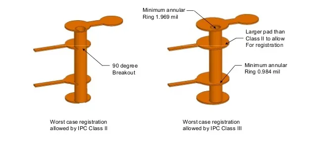
Q3: How do annular ring requirements compare in IPC Class 3 PCB and MIL-PRF-31032?
A3: IPC Class 3 specifies two mil external and one mil internal minimum annular rings for robust connections. MIL-PRF-31032 doubles these to five mil external and two mil internal, enhancing mechanical strength. Both prevent breakout issues in high-density designs. Engineers adjust pad sizes accordingly for compliance.
Q4: Can IPC Class 3 meet PCB for aerospace demands without MIL-Spec?
A4: Yes, IPC Class 3 with addendums like IPC-6012DS handles space avionics vibration and cycling. It provides high-reliability PCB performance accepted as COTS by agencies. MIL-Spec adds qualification layers for full military traceability. Selection depends on contract stipulations.
References
IPC-6012D — Qualification and Performance Specification for Rigid Printed Boards. IPC, 2015
IPC-6013 — Qualification and Performance Specification for Flexible Printed Boards. IPC
MIL-PRF-31032 — Performance Specification for Printed Circuit Boards/Printed Wiring Boards. DLA, 2024