Introduction
Single-sided printed circuit boards remain a staple in cost-sensitive applications such as consumer electronics, sensors, and basic control systems due to their simplicity and low manufacturing expenses. However, their single copper layer introduces unique challenges in managing electrical noise, which can degrade signal integrity and overall performance. Optimizing the layout for minimal noise is essential for electric engineers working on reliable designs under tight budgets. This article explores proven strategies to achieve single-sided PCB noise reduction, drawing on fundamental engineering principles and industry best practices. By focusing on structured layout techniques, engineers can mitigate common noise issues without transitioning to more complex multilayer boards. The goal is to deliver clear, actionable insights for designing robust single-sided PCBs that meet performance demands.
Understanding Noise in Single-Sided PCBs
Noise in single-sided PCBs arises primarily from electromagnetic interference, crosstalk, and power supply fluctuations because all traces, components, and ground connections share the same conductive plane. Unlike double-sided or multilayer boards, single-sided designs lack dedicated ground or power planes, forcing creative routing that often leads to inductive and capacitive coupling between signals. This shared layer amplifies susceptibility to external fields and internal switching transients, particularly in circuits with digital logic or analog sensors. Electric engineers must recognize that even low-frequency noise can propagate through long traces, causing erratic behavior in sensitive nodes. Addressing these issues early in the layout phase prevents costly redesigns and ensures compliance with performance specifications. Proper noise management enhances reliability across operating environments.
Key Sources of Noise and Their Mechanisms
The primary mechanisms of noise in single-sided PCBs include conducted noise from power lines, radiated emissions from high-speed traces, and ground bounce due to shared return paths. Crosstalk occurs when adjacent signal traces capacitively or inductively couple energy, with the effect worsening as trace separation decreases below recommended minimums. Power supply noise couples into signals through parasitic inductances in thin traces, especially when bypassing capacitors are distant from loads. Ground loops form when multiple ground paths create potential differences, injecting low-frequency hum into the circuit. These phenomena are exacerbated by the absence of shielding layers, making trace geometry and component placement critical. Understanding these interactions allows engineers to prioritize layout decisions that minimize coupling impedances.
Thermal and mechanical stresses can indirectly contribute to noise by altering trace resistances over time, though primary focus remains on electrical topology. Compliance with IPC-2221 guidelines for trace spacing helps quantify minimum clearances to reduce capacitive coupling by up to practical limits based on voltage levels. Engineers should model these effects using basic field theory to predict noise margins before fabrication.
Single-Sided PCB Grounding Techniques
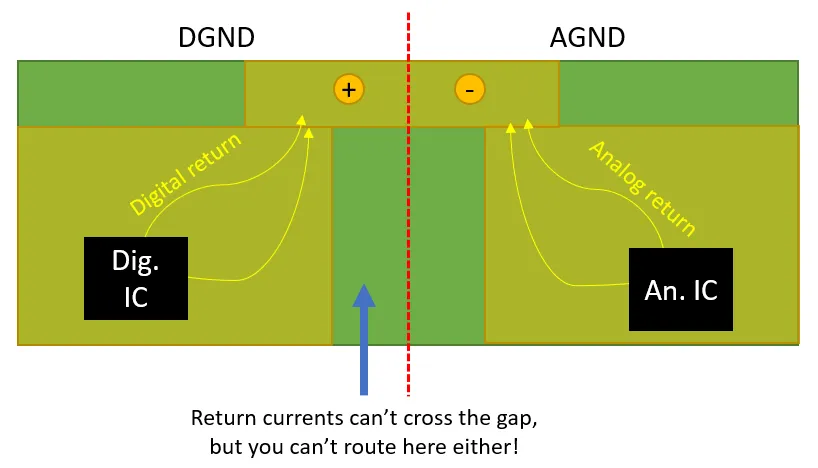
Effective single-sided PCB grounding techniques start with dedicating the largest possible contiguous copper area as a ground plane, even if it means routing signals around its periphery. This solid ground block provides a low-impedance return path, reducing voltage drops during transient currents and minimizing loop areas that act as antennas. Star grounding, where all ground connections converge at a single point near the power entry, prevents circulating currents that cause offsets between circuit sections. For mixed-signal designs, partition the ground into analog and digital zones connected at one low-noise point to avoid digital switching noise polluting sensitive analog paths. Avoid daisy-chaining grounds, as this increases series inductance and amplifies bounce. These methods form the foundation of single-sided PCB noise reduction by stabilizing reference potentials across the board.
Guard traces or stitching vias along edges can further enhance grounding by shielding sensitive traces from external interference, though via usage is limited on single-sided boards. Route power and ground returns as wide traces adjacent to signal lines to form transmission line-like structures with controlled impedance. Regular inspections during layout ensure no isolated ground islands form due to etching errors.
Role of Decoupling Capacitors in Noise Suppression
Single-sided PCB decoupling capacitors play a pivotal role in shunting high-frequency noise from power rails to ground before it reaches active components. Place these capacitors as close as possible to the power pins of integrated circuits, ideally within 0.1 inches, to minimize loop inductance in the power-ground path. Use a combination of ceramic capacitors for high frequencies and electrolytic ones for bulk storage, ensuring values match the IC's switching characteristics. Multiple capacitors in parallel can broaden the frequency response, compensating for single-sided layout constraints. Poor placement leads to resonant peaks where noise amplifies, underscoring the need for direct via or pad connections. Integrating decoupling effectively achieves substantial single-sided PCB noise reduction without additional layers.
Follow J-STD-001 requirements for component mounting to ensure mechanical stability, preventing capacitor leads from contributing stray inductance. Simulate the power distribution network mentally by considering trace lengths and capacitor ESR to optimize selection.
Signal Isolation Strategies for Single-Sided Layouts
Single-sided PCB signal isolation relies on physical separation, shielding traces, and deliberate routing to prevent mutual interference between high-speed and low-level signals. Maintain minimum trace-to-trace spacing per voltage and frequency guidelines, routing critical signals on inner paths away from board edges to reduce edge radiation. Use ground pours between signal groups as barriers, connecting them frequently to the main ground to drain induced currents. For analog signals, employ twisted pair routing or serpentine patterns if space allows, though straight shortest paths are preferable for digital. Filter networks at interfaces further attenuate ingress noise. These tactics collectively minimize noise in single-sided PCBs by controlling field distributions.
Avoid right-angle bends in traces, opting for 45-degree miters to reduce reflections and EMI hotspots. Group related signals together while isolating clocks and data lines from power distribution.
Routing and Layout Best Practices
Optimize routing by prioritizing short, direct paths for high-current and high-speed nets, relegating low-priority signals to longer routes. Fill unused copper areas with ground pours connected at multiple points to lower overall impedance and provide distributed capacitance. Component placement should cluster power-hungry devices near entry points, with noise-sensitive ones farthest from edges and connectors. Orient components to align traces parallel to the board length for better manufacturability and reduced stub lengths. Employ symmetry in differential pairs if applicable, even on single-sided boards. These practices systematically minimize noise in single-sided PCBs.
Adhere to IPC-6012 performance specifications during design review to validate layer integrity and trace quality post-layout. Balance copper distribution to prevent warpage that could alter clearances over time.
Verification Techniques for Low-Noise Layouts
Verify noise performance through bench testing with oscilloscopes probing key nodes under load, comparing waveforms to specifications. Conduct near-field EMI scans to identify radiating traces, iterating layout if hotspots exceed limits. Simulate parasitics using lumped models for quick feedback on decoupling efficacy. Thermal imaging complements this by revealing hot spots from poor grounding that indirectly boost noise via resistance changes. Prototype iterations refine techniques based on empirical data. These steps ensure the layout achieves targeted single-sided PCB noise reduction.
Conclusion
Optimizing single-sided PCB layouts for minimal noise demands a holistic approach integrating grounding techniques, strategic decoupling capacitor placement, signal isolation, and meticulous routing. Electric engineers benefit from these methods by delivering reliable, cost-effective boards that perform in demanding applications. Prioritizing low-impedance paths and partitioned zones addresses the inherent limitations of single-layer construction. Consistent application of these principles aligns with industry standards and elevates design quality. Ultimately, mastering these strategies enables engineers to minimize noise in single-sided PCBs without compromising simplicity or budget.
FAQs
Q1: What are the most effective single-sided PCB grounding techniques for noise reduction?
A1: Single-sided PCB grounding techniques include creating a large contiguous ground plane and using star topology to converge returns at one point near power input. Partition analog and digital grounds, connecting them at a single low-noise node to prevent cross-contamination. Wide ground traces adjacent to signals lower inductance, while avoiding daisy chains reduces bounce. These methods stabilize potentials and form the core of single-sided PCB noise reduction.
Q2: How do decoupling capacitors help minimize noise in single-sided PCBs?
A2: Decoupling capacitors shunt high-frequency noise from power pins to ground when placed within millimeters of IC loads, minimizing parasitic loop areas. Combine low-ESR ceramics for fast transients with higher-value types for sustained filtering. Parallel configurations extend bandwidth coverage. Proper single-sided PCB decoupling capacitors ensure clean rails, preventing supply noise from coupling into signals.
Q3: Why is signal isolation critical for single-sided PCB noise reduction?
A3: Signal isolation in single-sided layouts prevents crosstalk via increased trace spacing, ground barriers between groups, and routing sensitive lines inward from edges. Ground pours drain induced currents, while filters at boundaries block ingress. These steps control capacitive and inductive coupling inherent to shared layers. Effective single-sided PCB signal isolation maintains integrity in mixed-signal environments.
Q4: What routing practices best minimize noise on single-sided PCBs?
A4: Shorten high-speed traces, use 45-degree bends, and fill voids with connected ground pours to reduce inductance and radiation. Cluster components by function, isolating clocks from analogs. Symmetry aids differential signals. These practices optimize to minimize noise single-sided PCB designs face due to limited layers.
References
IPC-2221F - Generic Standard on Printed Board Design. IPC, 2020
IPC-6012E - Qualification and Performance Specification for Rigid Printed Boards. IPC, 2017
J-STD-001H - Requirements for Soldered Electrical and Electronic Assemblies. IPC, 2020


