Introduction
Printed circuit boards form the backbone of electronic assemblies, and material selection directly impacts performance, reliability, and manufacturability. FR-4 stands as the workhorse material for most applications due to its balance of properties and cost-effectiveness. PTFE, on the other hand, emerges as a specialized choice for demanding environments, particularly high-frequency operations. Electrical engineers must weigh factors like signal integrity, thermal stability, and budget constraints when deciding between these materials. This article compares PTFE and FR-4 across key attributes, highlighting PTFE PCB advantages disadvantages and scenarios where it serves as an FR4 alternative for high frequency. Factory insights reveal how material choices align with production standards to ensure robust outcomes.
Understanding FR-4: The Industry Standard
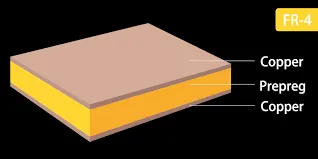
FR-4 consists of a woven glass fabric impregnated with epoxy resin, flame-retardant per UL94 V-0 classification. This composite delivers mechanical strength suitable for multilayer boards up to high layer counts. Its dielectric constant typically ranges from 4.0 to 4.8 at 1 GHz, supporting general-purpose designs below a few gigahertz. Electrical engineers appreciate FR-4 for consistent performance in consumer electronics, automotive controls, and industrial controls. However, its loss tangent around 0.02 introduces noticeable signal attenuation at higher frequencies. Factories standardize FR-4 processing, enabling high-volume production with reliable yields.
What Is PTFE and Why Consider It?
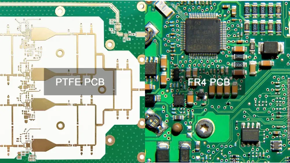
PTFE, or polytetrafluoroethylene, serves as a pure fluoropolymer base, often reinforced with glass or ceramics for PCB use. Known for its non-stick properties, PTFE excels in environments requiring chemical resistance and low friction. In PCB laminates, it provides a dielectric constant of 2.1 to 2.65, far lower than FR-4, minimizing signal propagation delays. This makes PTFE ideal for radar systems, satellite communications, and 5G infrastructure. Its loss tangent below 0.002 preserves signal integrity across microwave bands. Production involves specialized handling to maintain purity and prevent contamination.
Key Material Properties Comparison
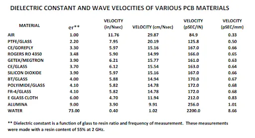
- Dielectric Constant (Dk @ 1-10 GHz) — FR-4: 4.0 - 4.8; PTFE: 2.1 - 2.65; Impact: Lower Dk in PTFE reduces phase shift
- Loss Tangent (Df @ 10 GHz) — FR-4: ~0.02; PTFE: <0.002; Impact: PTFE minimizes insertion loss
- Glass Transition Temp (Tg) — FR-4: 130°C - 170°C; PTFE: >260°C; Impact: PTFE suits elevated temperatures
- Moisture Absorption — FR-4: 0.1% - 0.2%; PTFE: <0.02%; Impact: Low absorption in PTFE stabilizes impedance
- Thermal Conductivity — FR-4: 0.3 - 0.4 W/mK; PTFE: 0.2 - 0.3 W/mK; Impact: Similar, but PTFE handles peaks better
These properties stem from inherent polymer structures, with FR-4 relying on cross-linked epoxy for rigidity and PTFE on fluorocarbon chains for insulation. Engineers use such tables during stackup planning to predict crosstalk and attenuation. Factory testing per IPC-TM-650 methods verifies these values before lamination.
PTFE PCB Advantages and Disadvantages
PTFE PCBs offer superior electrical performance, with low dielectric loss enabling clean signal transmission up to millimeter waves. Their chemical inertness resists solvents and acids encountered in harsh environments like aerospace. High thermal stability prevents degradation during soldering or operation near power amplifiers. Dimensional stability under thermal cycling reduces via failures in multilayer builds. However, PTFE's softness complicates drilling and plating, often requiring specialized carbide tools to avoid smear. Higher coefficients of thermal expansion in unreinforced variants demand careful matching with copper foils.
Disadvantages extend to mechanical fragility, where PTFE warps more easily than FR-4 during fabrication. Cost escalates due to raw material scarcity and custom processing, deterring low-volume runs. Engineers mitigate these by selecting glass-filled PTFE grades for better rigidity while retaining RF benefits. Factory experience shows hybrid approaches blending PTFE cores with FR-4 skins balance trade-offs.
PTFE PCB vs FR4 Cost Analysis
FR-4 remains the economical baseline, with laminate costs enabling prototypes under routine budgets. PTFE demands premium pricing from fluoropolymer sourcing and yield-sensitive manufacturing, often 5 to 10 times higher per square foot. Total PCB cost reflects not just material but extended lead times and tooling adjustments. For volume production, FR-4 scales efficiently, while PTFE suits niche high-reliability sectors. Engineers factor lifecycle savings from PTFE's durability against upfront premiums. Procurement teams evaluate PTFE PCB vs FR4 cost through total ownership models, prioritizing performance gates.
FR4 Alternative for High Frequency: When PTFE Shines
FR-4 suffices for digital signals below 3 GHz but falters in RF due to rising Df with frequency. PTFE emerges as the premier FR4 alternative for high frequency, sustaining low loss through Ka-band applications. In phased-array antennas or base stations, PTFE prevents bit-error rates from climbing. Standards like IPC-6012E qualify rigid boards for such performance, mandating thermal shock and electrical tests. Factories layer PTFE selectively in hybrid stacks, bonding to FR-4 via adhesives meeting IPC-4101 specifications for interface integrity.
Designers simulate impedance control early, as PTFE's low Dk shrinks trace widths for 50-ohm lines. Overetching risks increase without precise etch factors tuned to PTFE's uniformity. For automotive radar at 77 GHz, PTFE ensures phase matching across arrays. IPC-4101 slash sheets guide material selection, categorizing laminates by frequency suitability.
Fabrication and Best Practices
Processing FR-4 follows conventional flows: drill, desmear, electroless copper, pattern plate. PTFE requires plasma desmear or sodium etch to remove fluoropolymer residue, preventing adhesion failures. Lamination pressures stay lower to avoid resin flow issues in PTFE. Engineers specify oxide treatments for multilayer bonding per factory protocols.
Best practices include CTE-matched cores to curb warpage, tested via IPC-TM-650 2.4.39 methods. For high-frequency boards, control surface roughness to below 1 micron for low-loss copper. Hybrid designs use PTFE innerlayers with FR-4 outers, reducing overall cost while targeting RF zones. Qualification per IPC-6012E verifies conformance through cross-section analysis and continuity checks.
Troubleshooting Common Issues
Warpage plagues PTFE boards from asymmetric CTE, resolved by symmetric builds and bake-out cycles. Signal skew arises in FR-4 at multi-GHz speeds; switching to PTFE equalizes delays. Delamination risks heighten in humid storage, so precondition per JEDEC J-STD-020E before reflow. Factories audit moisture content routinely.
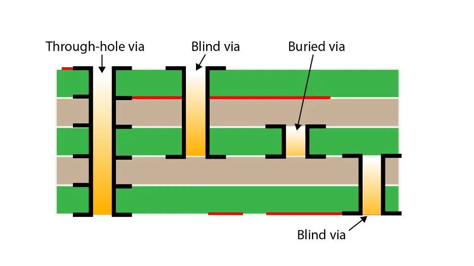
Impedance drift from moisture favors PTFE's hydrophobicity. Via stub effects demand blind/buried vias in both, but PTFE's stability aids tuning. Engineers log DFM feedback loops to refine specs.
Conclusion
Choosing between PTFE and FR-4 hinges on frequency demands, thermal profiles, and budgets. FR-4 delivers versatility for standard electronics, while PTFE unlocks high-frequency potential despite premiums. PTFE PCB advantages disadvantages tilt toward RF excellence offset by fabrication hurdles. As an FR4 alternative for high frequency, PTFE aligns with evolving 5G and beyond needs. Informed selection per standards ensures optimal performance and manufacturability.
FAQs
Q1: What are the main PTFE PCB advantages disadvantages?
A1: PTFE excels in low Dk and Df for minimal signal loss, high Tg for thermal resilience, and low moisture uptake for stable impedance. Disadvantages include elevated costs, mechanical softness complicating machining, and specialized processing needs. Engineers balance these for RF designs where performance justifies trade-offs. Factory yields improve with reinforced grades.
Q2: How does PTFE PCB vs FR4 cost compare?
A2: FR-4 offers low material and processing costs, ideal for high-volume general boards. PTFE incurs significantly higher expenses from premium resins and custom fabrication, often multiplying base prices. Total cost includes longer leads and tooling. Use PTFE where high-frequency gains offset premiums.
Q3: Is PTFE a reliable FR4 alternative for high frequency applications?
A3: Yes, PTFE surpasses FR-4 in high-frequency scenarios above 3 GHz due to lower loss tangent and stable Dk. It minimizes attenuation in microwave circuits like radars. Fabrication adapts via plasma treatments. Standards guide qualification for reliability.
Q4: When should electrical engineers select PTFE over FR-4?
A4: Opt for PTFE in RF/microwave where signal integrity trumps cost, such as 5G antennas. FR-4 fits lower frequencies with budget constraints. Hybrids combine strengths. Assess via simulations and prototypes.
References
IPC-6012E — Qualification and Performance Specification for Rigid Printed Boards. IPC, 2017
IPC-4101C — Specification for Base Materials for Rigid and Multilayer Printed Boards. IPC, 2016
JEDEC J-STD-020E — Moisture/Reflow Sensitivity Classification. JEDEC, 2014