Introduction
Automotive electronics have evolved rapidly, powering advanced driver-assistance systems, electric powertrains, and infotainment units in compact enclosures. These applications demand printed circuit boards that deliver high-density interconnects while enduring extreme vibration, temperature fluctuations, and long-term reliability. Sequential build-up PCBs address these needs by enabling finer features and buried vias without compromising structural integrity. Factory processes for automotive PCB sequential build-up focus on layer-by-layer construction to minimize stress accumulation common in traditional multilayers. This approach ensures automotive PCB reliability in harsh under-hood environments. Engineers specify these boards to meet performance targets in real-world vehicle dynamics.
What Are Sequential Build-Up PCBs and Why They Matter for Automotive Electronics
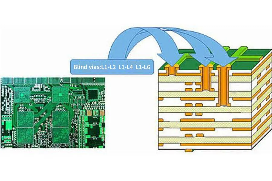
Sequential build-up, or SBU, PCBs involve fabricating multilayer boards by incrementally adding dielectric and copper layers on a central core, rather than laminating all layers simultaneously. This method supports blind and buried microvias, allowing higher routing density essential for modern automotive control units. In automotive applications, where space constraints meet high-speed signals and power delivery, SBU construction prevents via cracking from CTE mismatches during thermal excursions. Vibration resistant PCB sequential build-up designs incorporate reinforced via structures to withstand engine vibrations and road shocks. The relevance stems from industry shifts toward electrification and autonomy, requiring boards that integrate more functions reliably. Factories prioritize SBU for automotive PCB sequential build-up to achieve class 3 quality levels under demanding qualification flows.
Traditional all-layer-laminated boards often suffer warpage in high-layer counts due to asymmetric buildup, but SBU allows controlled symmetry. This matters for automotive PCB reliability, as uneven stress leads to delamination in thermal cycling. SBU processes also enable filled vias, reducing inductance for better signal integrity in radar and sensor modules. Engineers benefit from SBU's flexibility in stackup design, tailoring it to specific thermal and mechanical loads. Overall, this technology bridges miniaturization with durability in vehicle electronics.
Technical Principles of Sequential Build-Up for High-Reliability Automotive Applications
The SBU process begins with a thin core laminate, typically two to four layers, serving as the mechanical foundation. Subsequent build-up layers use photosensitive dielectrics laminated sequentially, followed by laser drilling for precise vias. Electroless copper seeding and electroplating form interconnects, with via filling using conductive or non-conductive epoxies to planarize surfaces for the next layer. This cycle repeats, enabling any-layer vias in advanced configurations. In high-temperature PCB sequential build-up, materials with matched CTE values prevent cracking under hood temperatures. Factories control lamination pressure and temperature to avoid voids, ensuring interlayer adhesion.
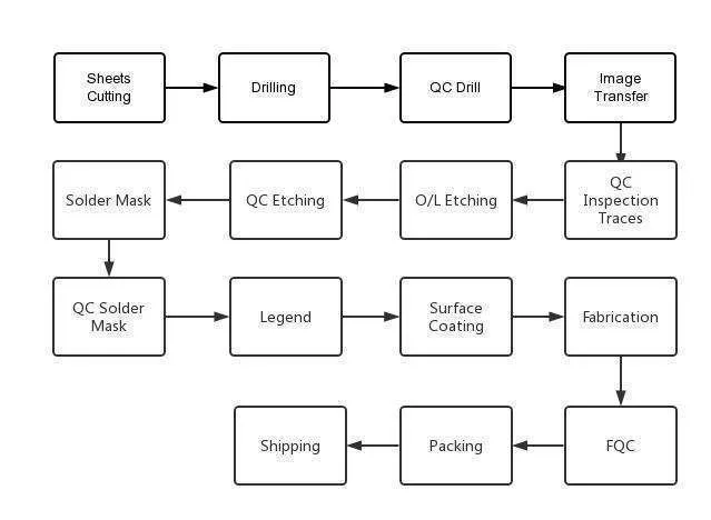
Vias in automotive SBU boards face cyclic stresses from power cycling and vibrations, so plating uniformity is critical. Laser ablation targets dielectric precisely, minimizing smear that could cause opens. Post-plating, outer layers receive imaging and etching for fine-line traces down to 50 microns. Thermal management integrates embedded planes for heat spreading in power electronics. Reliability hinges on dielectric integrity, resisting conductive anodic filamentation through low moisture absorption. These principles align factory outputs with long-life expectations in fleet operations.
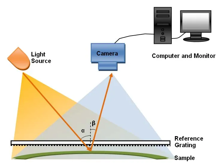
Sequential build-up differs from standard multilayers by decoupling lamination steps, reducing bow and twist. This is vital for vibration resistant PCB sequential build-up, as flatness aids assembly yields. Material choices emphasize high glass transition temperatures above 170 degrees Celsius for stability. Process-induced stresses are monitored via shadow moire for warpage prediction. Engineers model stackups to balance electrical and mechanical properties upfront.
Key Challenges in Automotive PCB Sequential Build-Up and Factory-Driven Solutions
One primary challenge in automotive PCB sequential build-up is via reliability under combined thermal and mechanical loads. Microvias can crack if plating cracks propagate during temperature ramps. Factories mitigate this through optimized via geometries and fill materials that absorb strain. Another issue is warpage from sequential asymmetry, addressed by symmetric outer builds and carrier clamping during lamination. High-temperature PCB sequential build-up demands resins with low Z-axis expansion to match copper. Routine cross-section analysis verifies void-free interfaces.
Vibration introduces fatigue in solder joints and traces, particularly resonant frequencies in engine bays. Vibration resistant PCB sequential build-up incorporates wider traces and anchored vias to dampen amplitudes. Factories perform panel-level strain gauging to correlate process parameters with field performance. CAF resistance requires ion-getter additives in dielectrics for humidity-prone underbody placements. Electrical testing post-build detects opens early, preventing field failures. These solutions stem from disciplined process controls.
Per IPC-6012E qualification requirements, automotive boards undergo bow and twist limits stricter than consumer grades. Sequential processes excel here by incremental stress relief between cycles. Yield optimization involves plasma desmear for clean via walls, enhancing pull strength. For power-dense designs, thick copper build-up layers handle currents without hotspots. Engineers collaborate on design rules to avoid drill breakout in stacked vias.
Best Practices for Manufacturing Vibration Resistant and High-Temperature Sequential Build-Up PCBs
Select laminates with CTE below 15 ppm per degree Celsius in Z-axis for automotive PCB reliability. Sequential lamination cycles use vacuum pressing to eliminate air entrapment. Laser systems calibrate for material ablation rates, ensuring via aspect ratios under 1:1. Post-via fill, polishing achieves flatness for imaging registration. Factories implement IPC class 3 visual criteria via automated optical inspection.
Thermal shock testing per IEC 60068-2 simulates rapid ramps, validating SBU integrity. Vibration profiles follow ISO 16750-3 for broad-spectrum loads up to 50g. Best practices include sequential build verification with time-domain reflectometry for impedance. Solder mask application protects fine features from handling damage. Final bare board testing covers 100% netlist with flying probes. These steps ensure automotive PCB sequential build-up meets operational lifespans over 10 years.
Stackup planning symmetrizes copper weights across the core. High-temperature PCB sequential build-up benefits from resin systems cured for minimal outgassing. Process traceability logs parameters for root cause analysis. Collaboration between design and fab teams refines DFM rules iteratively.
Conclusion
Sequential build-up PCBs stand out for automotive electronics by combining high density with exceptional reliability under vibration and heat. Factory expertise in layer-by-layer control addresses warpage, via fatigue, and CTE issues head-on. Standards-guided practices deliver boards ready for ADAS, EV inverters, and ECUs. Engineers gain confidence in miniaturization without sacrificing durability. Automotive PCB reliability hinges on these proven methods, future-proofing vehicle electronics.
FAQs
Q1: What is automotive PCB sequential build-up and how does it improve reliability?
A1: Automotive PCB sequential build-up constructs multilayers incrementally, enabling microvias and fine pitches for dense electronics. This reduces stress from lamination, enhancing resistance to thermal cycling and vibration. Factories achieve flatter boards with better via integrity, meeting class 3 standards. It supports high-speed signals in compact modules without delamination risks. Overall, it boosts automotive PCB reliability for long-term vehicle use.
Q2: Why choose high-temperature PCB sequential build-up for engine bay applications?
A2: High-temperature PCB sequential build-up uses low-CTE dielectrics and controlled plating for stability above 125 degrees Celsius. Sequential processing minimizes warpage from heat ramps, unlike all-lam methods. It ensures via fill withstands expansion mismatches. Factories verify with thermal profiling. This configuration maintains signal integrity in power electronics.
Q3: How does vibration resistant PCB sequential build-up handle road and engine stresses?
A3: Vibration resistant PCB sequential build-up features anchored microvias, filled structures, and symmetric stackups to dampen resonances. Factories test per mechanical load profiles, optimizing trace widths for fatigue life. Reinforced dielectrics prevent microcracks. This design sustains broad-spectrum vibrations over millions of cycles. Automotive PCB reliability improves in dynamic environments.
Q4: What testing ensures automotive PCB reliability in sequential build-up boards?
A4: Testing includes thermal cycling, random vibration, and electrical continuity checks post-fabrication. Factories assess warpage, via pull strength, and insulation resistance. Standards verify performance under combined loads. Cross-sections confirm process quality. These protocols confirm field durability for electronics.
References
IPC-6012E - Qualification and Performance Specification for Rigid Printed Boards. IPC, 2015
IEC 60068-2-14 - Environmental testing. Part 2-14: Test N: Change of temperature. IEC, 2009
ISO 16750-3:2012 - Road vehicles - Environmental conditions and testing for electrical and electronic equipment - Part 3: Mechanical loads. ISO, 2012


