Introduction
Single-sided printed circuit boards remain a staple in electronic hobbyist projects due to their simplicity and low cost. These boards feature conductive traces on only one side, making them ideal for basic circuits like LED drivers, simple sensors, or custom controllers. However, hobbyists often encounter issues such as broken traces, lifted pads, or faulty solder joints during prototyping or use. Learning single-sided PCB repair techniques empowers you to salvage boards instead of discarding them, saving time and resources. This single-sided PCB repair guide provides practical steps tailored for hobbyists, focusing on common fixes without advanced equipment. By following these methods, you can restore functionality and gain confidence in troubleshooting.
What Are Single-Sided PCBs and Why Repair Them?
Single-sided PCBs consist of a non-conductive substrate, typically FR-4, with a thin copper layer etched into patterns on one surface. Components mount on the opposite side, with leads passing through holes to connect via soldering. They excel in low-density designs where multilayer complexity is unnecessary, common in hobbyist radios, power supplies, or educational kits. Repairing them matters because these boards are prone to mechanical stress from bending, overheating during soldering, or vibration in projects.
Hobbyists benefit from repairs as they extend board life, reduce waste, and build skills transferable to more complex assemblies. Common failures include trace fractures from flexing or pad delamination from excessive heat. Addressing these promptly prevents cascading issues like open circuits or intermittent connections. Moreover, proper repairs align with industry practices, ensuring reliable performance in your circuits.
Common Failure Modes in Single-Sided PCBs
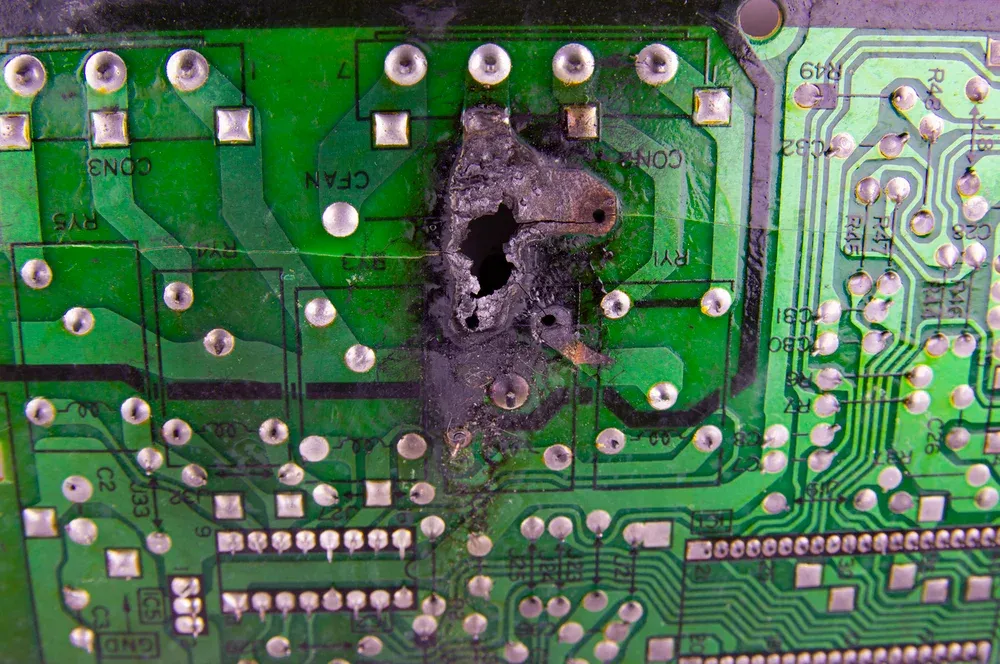
Trace breaks often occur at bends or stress points, especially if the board warps or experiences physical impact. Pads lift when solder overheats the copper-substrate bond, common during component removal without proper desoldering. Soldering defects, such as cold joints or insufficient wetting, arise from poor flux use or incorrect iron temperature. These issues disrupt current flow, leading to non-functional circuits.
Environmental factors like humidity can corrode traces over time, while mechanical wear from frequent handling accelerates damage. In hobby projects, prototyping errors like drill misalignment also contribute. Identifying failures starts with visual inspection and continuity testing using a multimeter. Early detection simplifies repairs and maintains project momentum.
Essential Tools and Materials for Hobbyists
A reliable soldering iron with temperature control, set between 300-350°C for most repairs, forms the core toolkit. Include solder wick or a desoldering pump for component removal, along with flux paste or liquid to improve solder flow. Thin enameled wire (28-32 AWG) serves as jumpers, and a sharp hobby knife or scraper exposes underlying copper.
A digital multimeter verifies continuity before and after repairs, while isopropyl alcohol cleans residues. Kapton tape protects nearby areas from heat, and magnifying glasses or a USB microscope aid precision. These affordable items suffice for most single-sided PCB soldering repairs at home. Many hobbyists also benefit from our dedicated DIY SMT stencils guide when preparing for repairs or small-batch work.
Single-Sided PCB Trace Repair Techniques
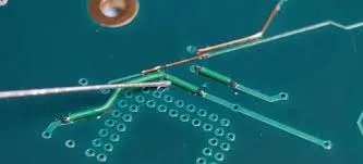
Begin trace repairs by cleaning the damaged area with isopropyl alcohol and inspecting with a multimeter for open circuits. Scrape away solder mask gently using a hobby knife to expose healthy copper on both sides of the break, avoiding substrate damage. Tin the exposed ends with a small amount of solder and flux for better adhesion.
For short gaps, bridge with a bead of fresh solder, ensuring it flows smoothly without bridging adjacent traces. Longer breaks require a jumper wire: strip enamel from ends, tin them, and solder securely to the exposed copper. Test continuity and apply insulating tape or conformal coating over the repair for durability. These steps follow guidelines in IPC-7711/7721 for conductor repairs, promoting mechanical strength.
Apply minimal heat to prevent further delamination, dwelling no more than 3-5 seconds per joint. If the trace lifts entirely, route the jumper along the board edge for strain relief. Multiple breaks may indicate board flexing, so reinforce with epoxy in future designs. This single-sided PCB trace repair method restores low-current paths effectively.
Single-Sided PCB Pad Repair Methods
Lifted pads demand careful assessment: if the pad detaches completely, locate the connected trace and expose it nearby. Clean the component hole and surrounding area, then solder a jumper wire from the hole to the exposed trace. For partial lifts, flatten the pad gently with tweezers and reattach using flux and low heat.
Advanced hobbyists can fabricate replacement pads from copper foil tape: cut to size, apply flux, and solder over the original site after cleaning. Bond with a drop of epoxy for security if needed, sanding smooth afterward. Verify solder fillet formation per IPC-A-610 criteria, ensuring 100% surround without cracks.
Avoid overloading repaired pads with heavy components; use mechanical support like eyelets for high-stress points. Test by tugging lightly post-cooling. These single-sided PCB pad repair techniques minimize downtime in prototypes.
Soldering Repair Techniques for Single-Sided PCBs
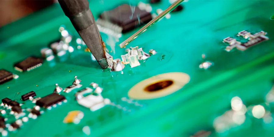
Cold solder joints appear dull or cracked; reflow by adding flux and reheating gently while adding fresh solder. For through-hole components, desolder using wick: apply flux, lay wick over joint, and iron until excess removes. Clean holes with a needle or compressed air.
Resolder with rosin-core solder, forming a shiny concave fillet that wets pad and lead fully, as outlined in J-STD-001. Inspect for bridges and remove with wick if present. Practice on scrap boards to master heat control, preventing pad damage.
Overheated joints require full desoldering: heat both sides alternately if double-sided access, but single-sided simplifies this. Replace components promptly to avoid oxidation. These how to repair single-sided PCB soldering issues ensure reliable connections.
Suggested Reading: SMT Stencils for Rework and Repair: Techniques and Considerations
Troubleshooting Tips and Best Practices
Always work in a static-safe area with grounded mats or wrist straps to protect sensitive parts. Preheat boards slightly for even heat distribution during repairs. Document changes with photos for complex boards.
If repairs fail repeatedly, consider board replacement, as substrate cracks may lurk. Use magnification for fine work and clean tools between sessions. Adhering to IPC standards elevates hobby repairs to professional levels.
Conclusion
Mastering single-sided PCB repair techniques transforms hobbyists from discarders to fixers, extending project life and honing skills. From trace jumpers to pad replacements and solder reflows, these methods address most issues with basic tools. Reference standards like IPC-7711/7721 ensure quality outcomes. Practice patiently, test thoroughly, and your circuits will thrive. Embrace repairs to fuel creativity in electronics.
FAQs
Q1: What is the best way to do single-sided PCB trace repair as a hobbyist?
A1: Identify the break with a multimeter, scrape to expose copper, and solder a tinned jumper wire across it. Use flux for clean joints and insulate afterward. This quick fix restores conductivity without special tools, ideal for prototypes. Test continuity post-repair to confirm success.
Q2: How do I repair a lifted pad on a single-sided PCB?
A2: Clean the area, expose the connected trace, and bridge with a wire from the hole to the trace. For full replacements, use copper foil soldered in place. Follow IPC-7721 guidelines for bonding strength. Avoid excessive heat to prevent further damage.
Q3: What are effective single-sided PCB soldering repair techniques?
A3: Reflow cold joints with flux and fresh solder, ensuring shiny fillets per J-STD-001. Desolder faults using wick, clean, and reinstall components. Control iron temperature to 320°C max. Inspect visually for bridges or voids.
Q4: Can hobbyists follow a single-sided PCB repair guide without professional training?
A4: Yes, basic tools and step-by-step methods like jumpers and reflow work well. Reference IPC-A-610 for joint acceptability. Practice on scraps builds proficiency. Complex multilayer boards may need experts, but single-sided suits home setups.
References
IPC-7711/7721D — Rework, Modification and Repair of Electronic Assemblies. IPC, 2024
IPC-A-610J — Acceptability of Electronic Assemblies. IPC, 2024
IPC J-STD-001J — Requirements for Soldered Electrical and Electronic Assemblies. IPC, 2024


