Introduction
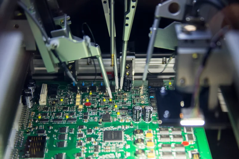
Flexible printed circuit boards, or flex PCBs, have become popular in hobby electronics projects due to their ability to bend and fit into tight spaces. From wearable gadgets to compact drones, these boards enable creative circuit designs that rigid PCBs simply cannot match. However, soldering flexible PCBs presents unique challenges for hobbyists, including heat management and mechanical stress that can lead to failures. Mastering soldering techniques for these boards ensures reliable connections in your projects. This guide focuses on practical methods tailored for electronic hobbyists, covering preparation, execution, and troubleshooting. With the right approach, you can tackle soldering flexible PCBs confidently for circuit repair or new builds.
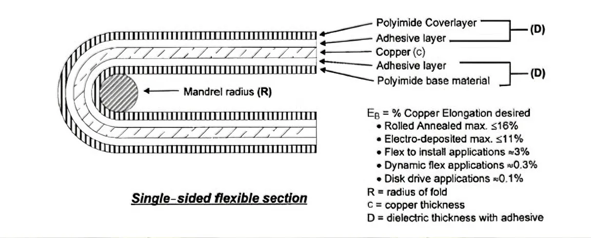
Flexible PCBs consist of thin layers of conductive traces on a bendable substrate, typically polyimide or polyester materials, allowing them to conform to irregular shapes. Unlike rigid boards, they lack the stiffness that makes soldering straightforward, which introduces risks like warping or delamination during the process. For hobbyists in electronics, understanding these boards opens doors to innovative applications such as flexible sensors or custom wearables. Proper soldering techniques prevent common pitfalls, ensuring your hobby projects last longer and perform reliably. Adhering to guidelines from standards like IPC-6013E helps maintain quality even in home setups. Ultimately, effective soldering on flexible PCBs elevates your skills in SMD soldering and circuit repair.
In hobby electronics, flex PCBs shine in projects requiring movement or miniaturization, but mishandled soldering can cause trace cracks or poor joints. Hobbyists often work without industrial equipment, relying on hand tools, so techniques must prioritize precision and minimal heat exposure. This matters because failed solder joints lead to frustrating circuit repair sessions. By focusing on best practices, you reduce rework time and build more durable prototypes. Flexible PCBs also demand design awareness, such as placing components away from bend zones, to support successful soldering.
What Are Flexible PCBs and Why Do Soldering Techniques Matter for Hobbyists?
Flexible PCBs consist of thin layers of conductive traces on a bendable substrate, typically polyimide or polyester materials, allowing them to conform to irregular shapes. Unlike rigid boards, they lack the stiffness that makes soldering straightforward, which introduces risks like warping or delamination during the process. For hobbyists in electronics, understanding these boards opens doors to innovative applications such as flexible sensors or custom wearables. Proper soldering techniques prevent common pitfalls, ensuring your hobby projects last longer and perform reliably. Adhering to guidelines from standards like IPC-6013E helps maintain quality even in home setups. Ultimately, effective soldering on flexible PCBs elevates your skills in SMD soldering and circuit repair.
In hobby electronics, flex PCBs shine in projects requiring movement or miniaturization, but mishandled soldering can cause trace cracks or poor joints. Hobbyists often work without industrial equipment, relying on hand tools, so techniques must prioritize precision and minimal heat exposure. This matters because failed solder joints lead to frustrating circuit repair sessions. By focusing on best practices, you reduce rework time and build more durable prototypes. Flexible PCBs also demand design awareness, such as placing components away from bend zones, to support successful soldering.
Technical Principles Behind Soldering Flexible PCBs
The core challenge in soldering flexible PCBs stems from their material properties: the substrate expands and contracts differently from copper traces under heat, risking delamination if temperatures rise too quickly. Solder joints themselves are rigid, so placing them in flex areas invites cracking over time due to repeated bending. Mechanical handling adds complexity, as unsupported boards can shift during soldering, leading to bridges or lifts. Heat transfer is uneven on thin flex layers, requiring controlled application to avoid scorching the base material. Flux plays a critical role here, removing oxides and improving wetting without residue that could stiffen the flex. These principles guide all soldering techniques, emphasizing speed, support, and minimal disturbance.
Thermal mismatch between components, solder, and the flex substrate demands careful profiling, much like in professional reflow but adapted for hand tools. Vibration or pressure from tweezers can tear fine pads, so gentle techniques are essential. Standards such as IPC-2223E outline design rules like larger pads and teardrop trace entries to distribute stress, which directly aids soldering success. Moisture absorption in flex materials exacerbates issues, as it turns to steam during heating, potentially causing voids. Pre-conditioning the board addresses this, aligning with reliability specs in IPC-6013E. Grasping these mechanisms empowers hobbyists to anticipate and mitigate risks in SMD soldering.
Essential Tools and Preparation for Soldering Flexible PCBs
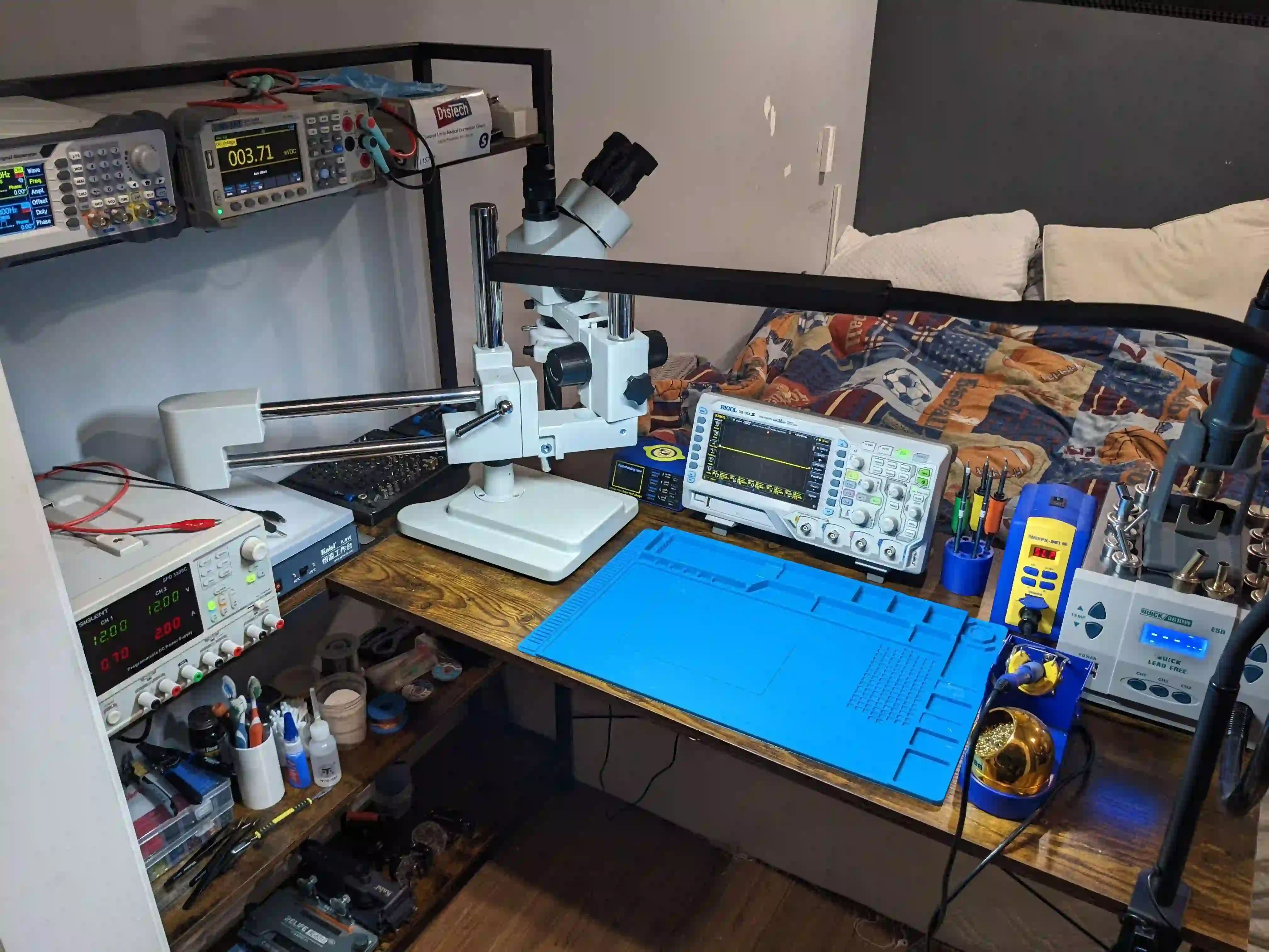
Start with a temperature-controlled soldering iron set to a moderate heat, fine-tip tweezers, and a good magnifier for precision work on small pads. Flux pen or liquid flux is non-negotiable for clean joints on flex surfaces, while isopropyl alcohol aids cleaning. A heat-resistant surface or jig to hold the flex flat prevents movement, and stiffeners like polyimide tape add support under solder areas. Desolder wick and pump prepare for fixes, crucial in circuit repair. Always work in a ventilated area and wear eye protection. Proper setup halves your troubleshooting time.
Preparation involves inspecting the flex PCB for damage and cleaning pads with alcohol to remove contaminants. Apply flux generously but wipe excess to avoid tackiness. If the board has been stored, allow it to acclimate to room temperature. Tinning the iron tip ensures efficient heat transfer without dragging. For SMD soldering, pre-tin component leads lightly. These steps, informed by J-STD-001 principles, set the foundation for reliable joints on flexible PCBs.
Practical Soldering Techniques for Hobbyists
Hand Soldering Through-Hole Components
For through-hole parts on flex PCBs, secure the board with tape or a jig to keep it flat. Heat the pad and lead simultaneously, feeding solder from the opposite side to flow evenly. Avoid dwelling on one spot; quick in-and-out motion minimizes heat buildup. Inspect for fillet shapes per soldering standards, ensuring no cracks. This technique suits larger hobby components like resistors in prototype builds. Practice on scrap flex to build speed.
SMD Soldering Techniques on Flexible PCBs
SMD soldering demands drag or point-to-point methods adapted for flex. Place components with tweezers, apply flux, then drag a tinned iron tip across pins while adding minimal solder. For multi-pin ICs, tack corners first, then fill gaps. Hot air tools offer gentle rework, blowing low heat from above while holding the board steady. Keep flex zones untouched to prevent stress. These hobby electronics favorites yield professional results without ovens.
For denser SMD arrays, use solder paste sparingly with a spatula, then reflow with a hot plate or heat gun at controlled distance. Position the flex on a flat metal surface for even heating. Monitor visually for reflow without bubbling. This mimics factory processes safely at home. Always cool naturally to avoid thermal shock.
Advanced Tips: Stiffeners and Strain Relief
Attach stiffeners before soldering to rigidify pad areas, using adhesive polyimide sheets cut to fit. This prevents pad lift during component insertion. After soldering, apply conformal coating or epoxy potting over joints for flex tolerance in moving parts. Route traces with curves, not sharp bends, per IPC-2223E guidelines. These enhance durability in wearable hobby projects.
Troubleshooting Common Issues in Flexible PCB Soldering
Cold joints appear dull and weak; re-flux and reheat briefly while adding solder. Delamination shows as bubbling; reduce dwell time and ensure dryness beforehand. Pad lifts from excessive force call for gentler handling and larger pads in future designs. Solder bridges on fine-pitch SMD need wick for cleanup, followed by flux and inspection. Cracked joints in flex zones indicate poor placement; reinforce or relocate. Systematic checks post-soldering catch 90% of issues early.
In circuit repair scenarios, test continuity before full disassembly. Heat-affected trace breaks require jumping with fine wire soldered carefully. Magnification reveals hidden defects like voids. Logging failures refines your soldering techniques over time.
Case Study: Repairing a Wearable Flex PCB
Consider a hobbyist fixing a fitness tracker's flex circuit after a drop caused intermittent connections. Inspection revealed cracked solder at a sensor pad in a bend zone. The repair involved adding a stiffener, cleaning with alcohol, fluxing, and re-soldering the SMD part using drag technique. Post-fix testing confirmed reliability through bends. This real-world circuit repair highlights preparation and support's value. Similar fixes apply to drone camera flexes or LED strips.
Conclusion
Soldering flexible PCBs rewards hobbyists with versatile electronics projects when approached methodically. Key takeaways include using flux liberally, supporting the board, minimizing heat exposure, and placing joints outside flex areas. Techniques like drag soldering for SMD and quick hand methods for through-hole deliver strong results. Troubleshooting builds expertise, turning challenges into successes. Reference standards like J-STD-001 for joint quality assurance. Dive into your next hobby electronics build with these soldering techniques for lasting circuits.
FAQs
Q1: What are the main challenges in soldering flexible PCBs for hobbyists?
A1: Flexible PCBs warp easily under heat and move during soldering, risking delamination or poor joints. Hobbyists must use jigs for stability and low-heat irons to match material limits. Flux helps wetting on thin traces. Following basic soldering techniques prevents most issues in SMD soldering or circuit repair.
Q2: How do I prepare a flex PCB for soldering techniques?
A2: Clean pads with alcohol, apply flux, and secure with tape or stiffeners. Acclimate the board to avoid moisture traps. Pre-tin tools for efficiency. This setup aligns with standards for reliable hobby electronics work on flexible PCBs. Inspect for damage first.
Q3: Can beginners do SMD soldering on flexible PCBs?
A3: Yes, start with drag soldering: flux pads, place parts, drag a tinned tip across pins. Use magnifiers and practice on scraps. Avoid flexing the board. These accessible techniques suit hobbyists tackling soldering flexible PCBs without pro gear.
Q4: What if my solder joints crack after bending the flex PCB?
A4: Cracks occur if joints are in bend zones; reinforce with potting or stiffeners. Redesign pads larger next time. Quick re-soldering after cleaning fixes most. This common circuit repair issue resolves with proper placement per design standards.
References
IPC J-STD-001J — Requirements for Soldered Electrical and Electronic Assemblies. IPC, 2024
IPC-6013E — Qualification and Performance Specification for Flexible/Rigid-Flexible Printed Boards. IPC, 2021
IPC-2223E — Sectional Design Standard for Flexible/Rigid-Flexible Printed Boards. IPC, 2019