Introduction
Flexible printed circuit boards have transformed electronics design by enabling compact, lightweight, and dynamically bendable interconnects in devices ranging from consumer gadgets to aerospace systems. Among flex PCB variants, adhesiveless flexible PCBs stand out for high-performance applications due to their superior construction that eliminates traditional adhesive layers between the copper conductors and dielectric substrate. This direct bonding approach enhances overall reliability and performance under demanding conditions. Engineers specifying these boards benefit from reduced risk of delamination and better thermal management, making them ideal for environments with repeated flexing, high temperatures, or high-frequency signals. As manufacturing processes evolve, adhesiveless flexible PCB benefits become increasingly relevant for mission-critical designs where failure is not an option. This article explores their construction, advantages, materials, manufacturing, and reliability strategies aligned with industry standards.
What Are Adhesiveless Flexible PCBs?
Adhesiveless flexible PCBs feature a laminate where copper foil bonds directly to a polyimide dielectric film without an intervening adhesive layer, unlike traditional adhesive-based flex cores that rely on acrylic or epoxy bonding agents. Common fabrication methods include casting polyimide resin onto copper foil, sputtering a thin copper seed layer onto the dielectric followed by electroplating, or using surface activation techniques like plasma or chemical treatment for direct adhesion. This results in a thinner, more homogeneous structure that maintains integrity during bending and thermal cycling. Rolled annealed copper foil is typically preferred for its ductility, allowing repeated flex cycles without cracking, while electrodeposited copper suits static applications. These boards come in single-sided, double-sided, or multilayer configurations, often with coverlay for protection instead of soldermask in flex zones. Per IPC-4204, adhesiveless constructions classify under metal-clad flexible dielectrics, ensuring consistent performance specs for qualification.
Key Adhesiveless Flexible PCB Benefits in High-Performance Scenarios
The primary adhesiveless flexible PCB benefits stem from eliminating adhesive-induced weaknesses, delivering thinner profiles that support tighter bend radii and enhanced flexibility. In dynamic applications, this construction reduces overall thickness by 0.001 to 0.002 inches compared to adhesive types, improving minimum bend capabilities and enabling complex 3D routing in space-constrained assemblies. Thermal performance excels as the homogeneous polyimide-copper interface withstands higher temperatures without adhesive degradation, suiting lead-free reflow and harsh environments. Electrical characteristics improve with better controlled impedance due to uniform dielectric properties between signal and reference planes, critical for high-speed signals. Mechanical stability benefits from low z-axis expansion, minimizing warpage and delamination risks during operation. These attributes position adhesiveless flexible PCBs as the choice for aerospace, telecommunications, and medical devices where reliability under stress is paramount.
Adhesiveless Flexible PCB Manufacturing Processes
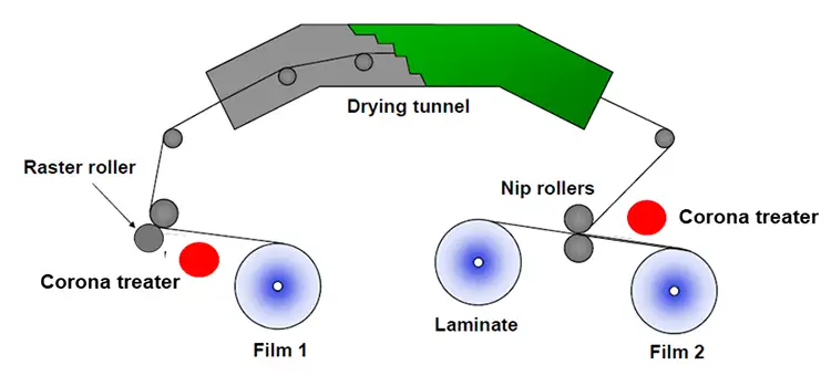
Adhesiveless flexible PCB manufacturing demands precise control to achieve direct bonding, starting with substrate preparation and progressing through lamination alternatives like casting or metallization. In the casting method, polyimide precursor solution applies directly to copper foil, cures under controlled heat, and forms a seamless laminate ready for imaging and etching. Sputtering involves depositing a seed copper layer via physical vapor deposition onto polyimide film, followed by electroplating to build conductor thickness, ideal for ultra-thin high-density designs. Direct bonding uses surface treatments such as ion beam or laser activation to enhance adhesion without intermediaries, followed by lamination under vacuum and pressure. These processes require specialized equipment to manage thin materials and prevent defects like pinholes or uneven plating. Factory insights emphasize cleanroom conditions and process validation to meet IPC-6013 performance classes for flex boards, ensuring plated through-hole integrity in multilayer stacks.
While more costly than adhesive methods due to complexity, adhesiveless production yields higher yields in high-layer counts by avoiding adhesive flow into vias during lamination.
Adhesiveless Flexible PCB Materials Selection
Core materials for adhesiveless flexible PCBs center on polyimide films for their balance of flexibility, thermal stability up to 400 degrees C, and low moisture absorption around 2.5 to 3 percent. These films meet IPC-4202 specifications for unclad base dielectrics, covering mechanical properties like elongation over 30 percent and electrical metrics such as dielectric constant of 3.2 to 3.5 at 1 MHz. Copper foils, typically 1/2 oz or 1 oz thick, use rolled annealed types for dynamic flex with elongation of 20 to 45 percent, aligning grain direction with bend axes to maximize cycle life. Coverlay materials, comprising polyimide with minimal adhesive, protect traces and maintain flex zones, with thicknesses starting at 0.001 inches. Selecting RA copper over ED prevents cracking in repeated bends, while polyimide grades ensure chemical resistance and dimensional stability under stress. Factory-driven material qualification focuses on peel strength above 6 lbs per inch post-thermal exposure for long-term reliability.
Enhancing Adhesiveless Flexible PCB Reliability
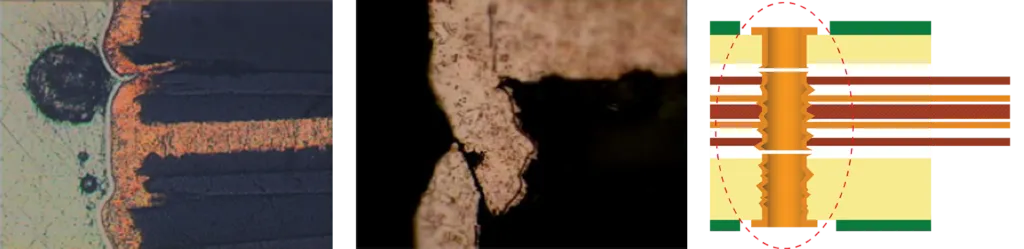
Adhesiveless flexible PCB reliability surpasses adhesive counterparts through reduced Z-axis stress cracking in plated through-holes, especially in high-layer designs exposed to thermal cycling. Homogeneous construction minimizes coefficient of thermal expansion mismatches, preventing delamination and maintaining signal integrity in high-frequency operations. Standards like IPC-6013 define performance classes and types, from single-sided Type 1 to multilayer rigid-flex Type 4, with requirements for plating thickness and bow-twist in rigid sections. Reliability testing includes bend cycle endurance, thermal shock, and humidity exposure to validate use conditions like continuous flexing or high temperatures over 105 degrees C. Factory practices incorporate coverlay registration to avoid creases or lifting, and stiffeners for mechanical support without compromising flex areas. These measures ensure robust performance in automotive sensors or RF modules.
Best Practices for Design and Manufacturing
Designers should align copper rolling direction with primary bend paths and incorporate teardrops at vias to distribute stress, optimizing for RA copper in dynamic zones. Limit copper thickness to 1 oz or less in flex areas to preserve bend radius, typically 6 to 10 times the total stack height. Manufacturing best practices include vacuum lamination for coverlay application and laser routing for precise feature openings with minimum webs of 0.015 inches. Validate materials per IPC-4202 for dielectric properties and conduct qualification per IPC-6013 classes matching end-use, such as Class 3 for high-reliability. Avoid stiffeners overlapping flex zones to prevent stress concentrations, and specify button plating for vias to reduce material in bends. These steps, drawn from production experience, maximize yield and field performance while leveraging adhesiveless flexible PCB benefits.
Conclusion
Adhesiveless flexible PCBs offer compelling advantages for high-performance applications through direct bonding that delivers superior flexibility, thermal endurance, and reliability without adhesive limitations. Their thinner profiles, enhanced plated hole integrity, and material stability make them indispensable for dynamic, high-density designs in challenging environments. Manufacturing and material choices, guided by standards like IPC-6013 and IPC-4204, ensure consistent quality from factory to field. Engineers can confidently specify these boards by following best practices in design alignment and testing. As demands for compact, robust electronics grow, adhesiveless constructions will continue driving innovation in interconnect technology.
FAQs
Q1: What are the main adhesiveless flexible PCB benefits for high-performance applications?
A1: Adhesiveless flexible PCB benefits include thinner construction for tighter bends, higher temperature resistance without adhesive degradation, improved plated through-hole reliability, and better dimensional stability. These traits support dynamic flexing, high-frequency signals, and harsh environments like aerospace or telecom. Factory production favors them for multilayer designs due to homogeneous layers reducing Z-axis stress.
Q2: How does adhesiveless flexible PCB manufacturing differ from adhesive-based processes?
A2: Adhesiveless flexible PCB manufacturing uses casting, sputtering, or direct bonding to eliminate adhesives, requiring precise vacuum lamination and surface activation. This contrasts with adhesive methods that involve heat-pressure bonding but risk via contamination. The result is higher process control for fine-pitch reliability, though at elevated cost, aligned with IPC-4204 specs.
Q3: What materials are used in adhesiveless flexible PCB constructions?
A3: Key adhesiveless flexible PCB materials feature polyimide dielectric films directly bonded to rolled annealed copper foil, with polyimide coverlay for protection. Polyimide provides thermal stability to 400 degrees C and elongation over 30 percent per IPC-4202. RA copper ensures ductility for repeated bends, suiting high-reliability dynamic applications.
Q4: How is adhesiveless flexible PCB reliability ensured in production?
A4: Adhesiveless flexible PCB reliability relies on qualification per IPC-6013, including bend cycles, thermal shock, and peel strength tests post-stress. Homogeneous bonding prevents delamination, while RA copper alignment extends flex life. Factory validation covers z-axis expansion control and coverlay integrity for Class 3 performance in demanding uses.
References
IPC-4202C — Specification for Flexible Base Dielectrics for Use in Flexible Printed Boards. IPC, 2022
IPC-4204 — Flexible Metal-Clad Dielectrics for Use in Fabrication of Flexible Printed Circuits. IPC
IPC-6013E — Qualification and Performance Specification for Flexible and Rigid-Flex Printed Boards. IPC, 2021