Introduction
Flexible printed circuits, often called flex PCBs, play a critical role in modern aerospace devices where space constraints and performance demands are extreme. Engineers designing electronic systems for aircraft and spacecraft prioritize materials that reduce weight without sacrificing reliability. Flex PCBs stand out as a lightweight material for aircraft, enabling significant mass savings compared to traditional rigid boards or wiring harnesses. Their ability to bend and conform addresses the unique challenges of aerospace environments, such as high vibration and thermal cycling. This article explores why flex proves ideal for these applications, focusing on practical engineering considerations for electric engineers. By understanding these advantages, teams can optimize designs for better efficiency and longevity.
What Are Flex PCBs and Why Do They Matter in Aerospace?
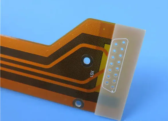
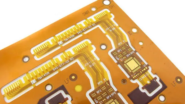
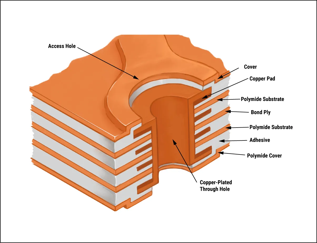
Flex PCBs consist of thin layers of conductive traces embedded in flexible substrates like polyimide, allowing them to bend repeatedly without failure. Flexible PCB Application spans across industries where compact design, motion tolerance, and weight reduction are critical, enabling engineers to replace rigid interconnects with dynamic, space-saving circuit layouts. Unlike rigid PCBs, which use stiff materials such as FR-4, flex circuits maintain electrical integrity in dynamic installations. In aerospace, every gram counts toward fuel efficiency and payload capacity, making lightweight material for aircraft a top priority. Flex PCBs replace bulky harnesses, reducing overall system weight by integrating circuits directly into curved structures. They matter because aerospace devices face constant motion, extreme temperatures from -55°C to over 125°C, and high-g forces during maneuvers. For electric engineers, selecting flex ensures circuits survive these conditions while fitting into tight spaces like avionics bays or wing assemblies.
The relevance extends to signal integrity, where flex minimizes electromagnetic interference through shorter trace lengths. Troubleshooting common issues like signal loss becomes simpler with flex's consistent impedance control. Aerospace standards demand high reliability, and flex meets these through proven construction methods. Engineers appreciate how flex simplifies assembly by eliminating connectors prone to loosening under vibration.
Key Technical Advantages of Flex in Aerospace Environments
Flex PCBs excel as a lightweight material for aircraft due to their thin profile and low-density substrates. Polyimide films used in flex weigh far less than epoxy laminates, allowing circuits to contribute minimally to total aircraft mass. This reduction directly impacts operational costs and range, as lighter electronics enable more fuel or sensors. In practice, flex integrates seamlessly into composite structures, following contours without adding structural penalties. Electric engineers often calculate weight savings during design reviews, confirming flex's superiority for high-performance aircraft.
Flexibility enables precise routing in confined areas, a hallmark of flexible material aerospace circuits. Circuits can fold, twist, or wrap around components like actuators or sensors, maximizing space utilization. This conformity reduces the need for custom adapters, streamlining prototyping and testing. During vibration testing, flex absorbs energy through material deflection rather than transmitting it to solder joints. Results show flex maintains continuity where rigid boards crack, providing a troubleshooting edge in iterative designs.
Thermal stability further sets flex apart, with substrates enduring rapid coefficient of thermal expansion mismatches. Aerospace devices cycle through altitudes causing pressure and temperature swings, and flex's low thermal mass aids quick stabilization. Engineers verify this through cross-section analysis, ensuring no delamination occurs. Combined with fine-line etching capabilities, flex supports high-density interconnects for complex avionics.
Vibration resistance proves crucial, as aircraft encounter frequencies from engine hum to turbulent airflow. Flex's layered construction distributes stress evenly, preventing fatigue in traces. Practical tests reveal flex outperforms wired assemblies in endurance, reducing failure modes like fretting corrosion. For electric engineers, this means fewer field returns and extended mean time between failures.
Reliability Mechanisms and Standards Compliance
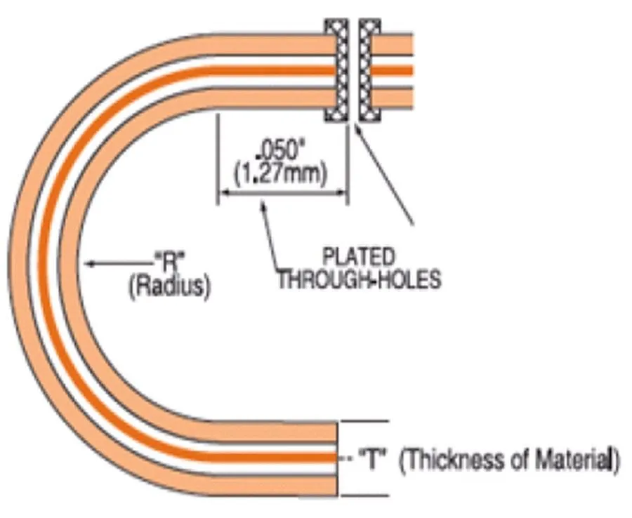
Reliability in flex stems from robust material properties and precise manufacturing. Adhesive-less laminates bond copper directly to polyimide, eliminating weak interfaces prone to peeling. This construction aligns with IPC-6013E requirements for qualification, ensuring flex withstands mechanical flexing cycles. Electric engineers reference such standards to specify bend radii and layer counts, avoiding common pitfalls like trace cracking in high-flex zones.
IPC-2223E guides design for flexible material aerospace circuits, dictating spacing and via placement to prevent shorts during deployment. Compliance involves simulating folds early in the design phase, using finite element analysis for stress prediction. Troubleshooting often uncovers issues from inadequate coverlay thickness, which IPC standards address through tolerance specs. These guidelines help teams achieve Class 3 performance, mandatory for aerospace.
Environmental sealing enhances longevity, with flex encapsulated to resist humidity and contaminants. In aircraft, where condensation forms during pressure changes, this prevents dendritic growth on traces. Engineers apply conformal coatings judiciously, balancing flexibility with protection. Overall, standards-driven design yields circuits that outlast mission profiles.
Best Practices for Implementing Flex in Aerospace Designs
Start with material selection tailored to aerospace demands, prioritizing high-Tg polyimides for thermal extremes. Collaborate with fabricators early to define stackups, ensuring compatibility between flex and rigid sections if hybrid. Use dynamic bend modeling to set minimum radii, typically 10 times trace width, preventing early fatigue. Electric engineers benefit from iterative prototypes, testing under simulated flight conditions.
Assembly requires careful handling to avoid creasing substrates. Employ low-stress soldering per J-STD-001, minimizing heat exposure that could warp flex areas. For troubleshooting, inspect flex zones with cross-polarization microscopy to detect voids. Integrate strain gauges during qualification to monitor real-time performance.
Routing strategies optimize for impedance, with ground planes shielding sensitive signals. Avoid sharp bends near connectors, using fan-out patterns for even stress. In production, panelize designs efficiently while maintaining IPC-compliant registration. These practices reduce rework and accelerate certification.
Design reviews should include reliability predictions using acceleration factors from standards testing. Document bend cycles and environmental exposures for traceability. Partnering with certified processes ensures audit readiness. This systematic approach delivers robust flexible material aerospace circuits.
Challenges and Troubleshooting Insights
Common challenges include signal skew in long flex runs, addressed by controlled dielectric thickness. Vibration-induced micro-cracks appear as intermittent opens; mitigate with wider traces in flex areas. Thermal expansion differences in rigid-flex transitions cause reliability issues, solved by tapered zones per IPC-2223E.
Troubleshooting starts with electrical testing under flex, using flying leads for continuity checks. Visual inspection reveals coverlay lifts, often from over-etching. For electric engineers, daisy-chain monitors during vibration sims pinpoint weak points. Adjusting copper weights balances flexibility and current capacity.
Creepage in humid environments demands precise spacing, verified through salt fog exposure. Hybrid assemblies risk z-axis misalignment; use fiducials for alignment. These insights, drawn from field experience, guide refinements for mission-critical apps.
Conclusion
Flex PCBs emerge as the ideal choice for aerospace devices through unmatched lightweight material for aircraft properties and adaptability. Their flexibility, vibration tolerance, and reliability address core engineering challenges in tight, harsh spaces. Standards like IPC-6013E and IPC-2223E provide the framework for success, ensuring designs meet performance thresholds. Electric engineers gain practical tools for integration, from stackup optimization to testing protocols. Adopting flex not only cuts weight and volume but enhances overall system resilience. Future aerospace innovations will lean heavily on these circuits for next-generation efficiency.
FAQs
Q1: Why choose flex PCBs as a lightweight material for aircraft over rigid boards?
A1: Flex PCBs use thin polyimide substrates that drastically reduce mass while maintaining electrical performance. They eliminate heavy wiring harnesses, fitting conformal shapes in aircraft structures. This makes them essential for fuel-efficient designs. Engineers troubleshoot weight issues early by modeling total system mass, confirming flex's advantages in dynamic environments. Compliance with IPC standards ensures durability.
Q2: How does flexible material aerospace circuits handle vibration better?
A2: Flexible material aerospace circuits distribute stress through deflection, avoiding brittle failure in rigid joints. Traces in polyimide endure high-cycle bending without cracking. Practical testing simulates flight vibrations, verifying continuity. Electric engineers monitor with accelerometers, adjusting designs for peak resilience. This outperforms traditional assemblies in longevity.
Q3: What standards guide flex PCB design for aerospace?
A3: IPC-6013E qualifies flex for performance under mechanical stress, while IPC-2223E details sectional layouts. These ensure lightweight material for aircraft meets Class 3 reliability. Engineers apply them for bend radii and transitions. Troubleshooting aligns prototypes to these specs, preventing field issues.
Q4: Can flex PCBs integrate with rigid sections in aerospace devices?
A4: Yes, rigid-flex hybrids combine stability with flexibility, ideal for avionics. Transitions use controlled overlaps to manage CTE mismatch. Assembly follows J-STD-001 for solder integrity. Electric engineers prototype to resolve alignment challenges, optimizing for vibration-prone installs.
References
IPC-6013E — Qualification and Performance Specification for Flexible/Rigid-Flexible Printed Boards. IPC, 2021
IPC-2223E — Sectional Design Standard for Flexible/Rigid-Flexible Printed Boards. IPC, 2020
J-STD-001H — Requirements for Soldered Electrical and Electronic Assemblies. IPC, 2020