Introduction
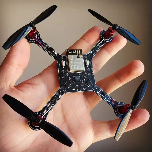
Building your own drone opens up exciting possibilities for electronic hobbyists, from aerial photography to custom racing setups. At the heart of any reliable drone lies its printed circuit board, or PCB, which manages power distribution, signal processing, and wireless communication. For hobbyists pushing performance boundaries, standard FR-4 PCBs often fall short due to signal losses and thermal issues in high-frequency applications. This is where Rogers PCB for drones shines, offering materials optimized for high-performance drone electronics. In this guide, we explore drone PCB design principles, focusing on how Rogers materials enhance RF control circuits and enable long-range drone communication. Whether you are prototyping a FPV racer or a surveying drone, selecting the right PCB material can make the difference between a sluggish flyer and a responsive machine.
Why Rogers PCB Matters for Drone Builds
Rogers PCBs refer to high-frequency laminates designed for demanding RF and microwave applications, providing superior electrical performance over traditional materials. In drone projects, these boards handle the intense demands of telemetry, video transmission, and control signals operating at GHz frequencies. Hobbyists notice immediate benefits in reduced signal attenuation, which translates to clearer video feeds and more stable control links over extended ranges. High-performance drone electronics require materials with low dielectric loss and consistent permittivity to minimize phase shifts and maintain signal integrity. Without such properties, long-range drone communication suffers from interference and dropouts, frustrating flight tests. Choosing Rogers PCB for drones ensures your custom build meets the rigors of real-world flying conditions.
Drones operate in dynamic environments with vibration, temperature swings, and weight constraints, amplifying the need for robust PCB choices. Standard laminates can warp or delaminate under these stresses, leading to intermittent failures mid-flight. Rogers materials excel here with their dimensional stability and high glass transition temperature, supporting reliable operation. For electronic hobbyists, this means fewer redesign iterations and more time enjoying successful flights. Integrating Rogers into your drone PCB design also future-proofs your project for advanced features like 5G modules or multi-band antennas. Ultimately, performance matters because it directly impacts flight time, range, and safety.
Key Technical Principles in Drone PCB Design with Rogers Materials
Drone PCB design revolves around balancing size, weight, and electrical performance, especially for RF-heavy sections. High-frequency signals in RF control circuits demand controlled impedance traces to prevent reflections and losses. Rogers laminates maintain a stable dielectric constant across frequencies, unlike FR-4 which varies significantly, ensuring predictable signal propagation. This stability is crucial for long-range drone communication, where even minor mismatches can degrade link budgets. Hobbyists must consider stackup configurations that hybridize Rogers cores with FR-4 for cost-effective power planes while isolating RF sections.
From a rogers PCB application perspective, these material choices directly support real-world drone systems where RF performance, weight efficiency, and reliability must be optimized simultaneously.
Thermal management forms another pillar, as drone motors and batteries generate heat that propagates through the PCB. Rogers materials offer low coefficients of thermal expansion, reducing stress at vias and component pads during temperature cycles. According to IPC-6012E, qualification for rigid printed boards emphasizes performance under thermal shock, a test Rogers excels in for aerospace-like applications. Vibration resistance is equally vital; drones endure constant mechanical stress, so PCB layouts incorporate ground pours and stitching vias to enhance structural integrity. Signal integrity analysis reveals how Rogers' low loss tangent minimizes insertion loss, preserving power for antennas and receivers. These principles guide hobbyists toward designs that fly farther and more reliably.
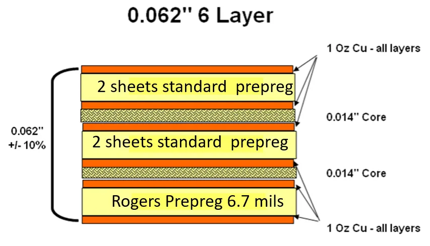
Power distribution networks in drones require careful routing to avoid noise coupling into sensitive RF paths. Rogers PCB for drones supports fine-line etching down to tight tolerances, enabling compact layouts for brushless motor drivers and flight controllers. Electromagnetic interference mitigation uses embedded shielding and guard traces, leveraging the material's uniform properties. For multi-layer boards, prepreg selection matches the core's characteristics to prevent Z-axis inconsistencies. Hobbyists benefit from simulating these effects early, focusing on return path minimization for clean RF control circuits.
Best Practices for Implementing Rogers PCB in Your Drone Project
Start your drone PCB design by defining requirements: frequency bands, power levels, and environmental exposures. Select Rogers grades suited to your needs, prioritizing low-loss variants for RF control circuits above 1 GHz. Prototype with a simple two-layer board to validate signal performance before scaling to multi-layer high-performance drone electronics. Use impedance calculators to target 50-ohm traces for communication lines, adjusting width and height based on the material's effective epsilon. Fabricate small panels to test assembly yields, ensuring compatibility with standard SMT processes.
Layout strategies emphasize segregation: dedicate inner layers for RF with minimal vias, routing DC power on outer layers. Incorporate test points for S-parameter measurements post-assembly, verifying long-range drone communication margins. Thermal vias under high-power ICs dissipate heat effectively through Rogers' high thermal conductivity paths. Follow J-STD-001 for soldering requirements, as high-frequency boards demand precise reflow profiles to avoid microcracks. Hobbyists should iterate with thermal imaging during ground tests to spot hotspots early.
Component selection ties into PCB capabilities; choose RF-rated passives with tight tolerances for filters in the communication chain. Enclosure integration prevents detuning of antennas, so model the full assembly in 3D. For longevity, apply conformal coating per IPC-A-600K acceptability criteria, protecting against humidity in outdoor flights. Troubleshooting common issues like intermittent RF dropouts often traces to ground loops; resolve with solid pours and capacitor decoupling networks. These practices turn hobbyist prototypes into flight-worthy drones.
Firmware integration completes the hardware; ensure GPIO routing avoids RF zones to prevent digital noise injection. Battery management circuits benefit from Rogers' stability under high currents, reducing voltage droop. Flight testing protocols include range checks and RSSI logging to quantify improvements over FR-4 baselines. Document your stackup and Gerber files meticulously for future revisions. By adhering to these best practices, electronic hobbyists achieve professional-grade results without enterprise budgets.
Troubleshooting Common Challenges in High-Performance Drone Electronics
Even with Rogers PCB for drones, issues arise during integration. Signal crosstalk in dense layouts manifests as erratic control response; mitigate by increasing trace spacing and adding shielding fences. Overheating in power stages warps thin boards, so thicken copper weights judiciously while monitoring via reliability. Antenna mismatch shortens range, addressed by tuning stubs or adding matching networks during bench tests. Vibration-induced fatigue cracks solder joints; reinforce with underfill or potting for critical modules.
Long-range drone communication failures often stem from multipath fading, countered by diversity antennas on separate Rogers sections. EMI compliance testing reveals radiated emissions; suppress with ferrite beads and filtered connectors. Battery voltage sag under load affects stability, so parallel decoupling caps stabilize rails. Post-mortem analysis of crashed prototypes highlights mechanical weaknesses, prompting chassis-mounted dampers. Graceful troubleshooting keeps projects on track, turning setbacks into learning opportunities for hobbyists.
Conclusion
Rogers PCB elevates drone builds from basic to high-performance, tackling the core challenges of RF control circuits and long-range drone communication. By understanding material properties and applying structured design practices, electronic hobbyists craft reliable, efficient flyers. Key takeaways include prioritizing low-loss stackups, rigorous thermal management, and iterative testing aligned with industry standards. Your custom drone not only performs better but inspires further innovations in the hobby space. Dive into prototyping with confidence, and watch your creation soar.
FAQs
Q1: What makes Rogers PCB ideal for drone PCB design?
A1: Rogers materials provide low dielectric loss and stable permittivity, essential for high-performance drone electronics. They support precise impedance control in RF control circuits, reducing signal degradation at high frequencies. Hobbyists achieve longer ranges and clearer telemetry compared to standard laminates, with better thermal stability for sustained flights. This choice simplifies troubleshooting in dynamic environments.
Q2: How does Rogers PCB improve long-range drone communication?
A2: Low loss tangent in Rogers laminates minimizes attenuation over distance, preserving signal strength for video and control links. Consistent dielectric properties ensure reliable phase matching in antennas and transceivers. Hobbyists report extended line-of-sight ranges without amplifiers, thanks to optimized trace routing. Pair with proper ground planes for maximum effectiveness.
Q3: What are best practices for RF control circuits on Rogers PCB for drones?
A3: Segregate RF traces from digital lines using dedicated layers and guard rings to prevent crosstalk. Control 50-ohm impedance with precise width calculations based on material specs. Test S-parameters early to verify insertion loss below 1 dB per inch. Decouple power supplies thoroughly for clean operation in flight.
Q4: Can hobbyists mix Rogers and FR-4 in drone PCB design?
A4: Yes, hybrid stackups use Rogers for RF sections and FR-4 for power planes, balancing cost and performance. Ensure prepreg matching to avoid Z-axis CTE mismatch. This approach suits high-performance drone electronics without full premium material costs. Validate transitions with TDR measurements during prototyping.
References
IPC-6012E — Qualification and Performance Specification for Rigid Printed Boards. IPC, 2017
IPC-A-600K — Acceptability of Printed Boards. IPC, 2020
J-STD-001 — Requirements for Soldered Electrical and Electronic Assemblies. IPC, 2020


