Introduction
Metal core printed circuit boards, or MCPCBs, serve critical roles in applications demanding superior heat dissipation, such as power electronics, LED lighting, and automotive systems. Selecting the appropriate thickness for an MCPCB directly influences its thermal performance, mechanical reliability, and overall functionality. Engineers must balance these factors to meet PCB thermal requirements while ensuring mechanical strength PCB demands are satisfied. Common materials like aluminum or copper bases define the core, with total board thicknesses typically ranging from 0.8 mm to 3.0 mm depending on the design. This guide provides factory-driven insights into MCPCB thickness calculation, drawing from established manufacturing principles to help electric engineers optimize their designs. Proper thickness selection prevents issues like overheating or structural failure in demanding environments.
Understanding Metal Core PCBs and the Role of Thickness
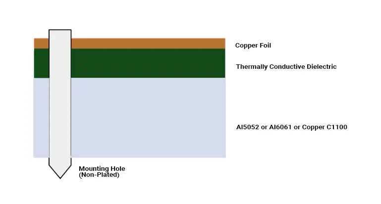
MCPCBs differ from standard FR-4 boards by incorporating a thick metal substrate, usually aluminum or copper, bonded to a thermally conductive dielectric and topped with copper circuitry. This construction enables efficient heat transfer from components to a heatsink or chassis. Thickness in MCPCBs refers to the overall board height, dominated by the metal core, which can vary significantly based on application needs. Aluminum PCB thickness often starts at 0.8 mm for lighter duties, while copper PCB thickness may exceed 2 mm for high-current scenarios. Factory processes align with standards like IPC-2221A to ensure design integrity from thermal management to mechanical stability. Why does thickness matter? It governs heat spreading, board rigidity, and warpage resistance during thermal cycling.
In manufacturing, the metal core provides the primary thermal pathway, with the dielectric layer acting as a bottleneck due to its lower conductivity. Thicker cores enhance mechanical strength PCB by reducing flexure under vibration or handling. However, excessive thickness increases material costs and weight, potentially complicating assembly. Engineers evaluate PCB thermal requirements first, as inadequate dissipation leads to component failures. Standards such as IPC-6012D specify performance qualifications for rigid boards including metal cores, emphasizing uniform layer distribution around the core in multilayer designs. Balancing these elements ensures reliable production yields.
Key Technical Principles Influencing MCPCB Thickness
Thermal Management Fundamentals
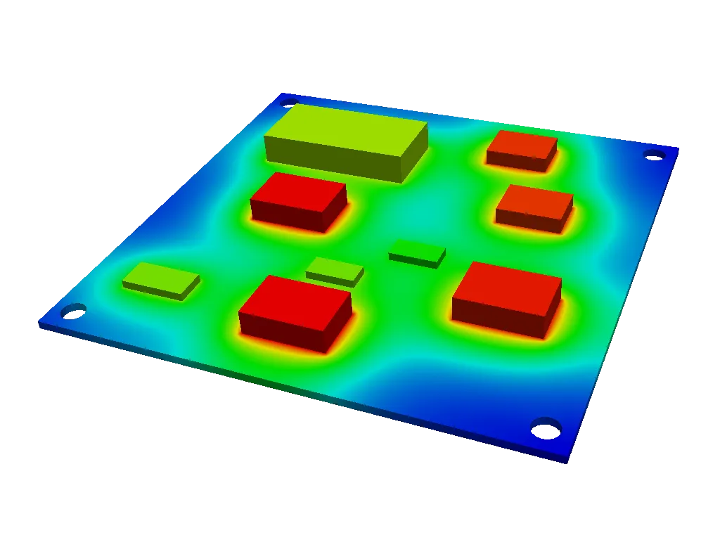
Effective thermal performance hinges on minimizing thermal resistance across the board stackup. The thermal resistance formula, R_th = d / (k * A), where d is the dielectric thickness, k is thermal conductivity, and A is the area, underscores why thinner dielectrics, typically 75 to 150 μm, are preferred for high-power applications. The metal core's thickness primarily aids lateral heat spreading to the board edges or vias. Aluminum cores with thicknesses from 1.0 mm to 1.5 mm suit most LED arrays, offering conductivity around 200 W/m·K. Copper cores, with higher conductivity near 400 W/m·K, allow thinner profiles for equivalent performance but demand careful CTE matching to avoid delamination. PCB thermal requirements dictate that engineers simulate junction temperatures under load to validate choices.
Factory insights reveal that thicker cores improve overall heat capacity, stabilizing temperatures during transients. However, the dielectric's properties dominate vertical conduction, so its thickness must align with voltage isolation needs. IPC-2221A provides guidelines for thermal design, including current-carrying capacity adjusted for metal core enhancements. Overly thick dielectrics increase hotspot risks, while too thin compromises electrical integrity. Integrating thermal vias further optimizes flow, but core thickness sets the baseline for dissipation efficiency.
Mechanical Strength Considerations
Mechanical strength PCB is paramount in environments with vibration, shock, or mounting stresses. Thicker metal cores, such as 1.5 mm to 2.0 mm aluminum, boost flexural modulus, reducing deflection under load. This prevents microcracks in solder joints or traces during operation. Copper PCB thickness offers superior stiffness due to higher Young's modulus, ideal for rugged applications. However, CTE mismatch between the core (around 23 ppm/°C for aluminum) and dielectric (15-20 ppm/°C) induces warpage, especially in larger panels. Thinner boards exacerbate this, leading to bow and twist beyond acceptable limits per manufacturing tolerances. For a complete breakdown of how core thickness integrates with full stackup design, refer to our beginner's guide to designing an aluminum PCB.
Standards like IPC-A-600K define acceptability criteria for warpage, typically under 0.75% for class 2 boards. Factory lamination processes control residual stresses by symmetric layering around the core. Engineers perform finite element analysis to predict deformation under thermal-mechanical cycles. Thicker profiles mitigate these risks but may require adjusted drilling parameters for vias. Balancing mechanical strength PCB with thermal needs ensures long-term reliability without over-engineering.
Electrical and Manufacturing Implications
While MCPCBs are often single- or double-sided, thickness affects trace impedance and high-frequency performance minimally compared to thermal factors. Copper thickness on the circuit layer, usually 1 to 3 oz (35 to 105 μm), must support current density without excessive heating. Thicker base metals complicate via formation and plating uniformity, per IPC-6012D requirements for hole wall integrity. Manufacturing tolerances for total thickness are ±10% for standard boards, tightening to ±5% for precision apps. Aluminum PCB thickness variations impact heatsink fit, while copper demands anti-oxidation treatments.
Best Practices for MCPCB Thickness Calculation and Selection
Start MCPCB thickness calculation by quantifying power dissipation and target junction temperatures. Use simulation tools to model heat flow, iterating core and dielectric thicknesses until thermal margins meet specs. For aluminum PCB thickness, select 1.2 mm cores for moderate power (up to 50 W), scaling to 1.6 mm for higher loads. Copper PCB thickness can be 0.8 mm for dense heat sources due to better spreading. Factor in mechanical strength PCB via stiffness calculations; aim for deflection under 0.5 mm under expected forces.
Thermal: thinner thickness benefit = lower dielectric R_th; thicker thickness benefit = better lateral spreading.
Mechanical: thinner thickness benefit = lighter weight; thicker thickness benefit = higher rigidity and less warpage.
Cost/Manufacturing: thinner thickness benefit = lower material use; thicker thickness benefit = standard tooling compatibility.
Electrical: thinner thickness benefit = flexible bending; thicker thickness benefit = stable impedance.
Consult factory capabilities early; not all lines handle cores over 2 mm efficiently. Validate prototypes with thermal cycling per IPC-MC-324 performance specs for metal core boards. Incorporate filled vias or pads under hotspots to enhance conduction.
For high-reliability apps, symmetric stackups around the core prevent camber. Document PCB thermal requirements in specs, including max ΔT across the board. Learn how dielectric thickness directly influences thermal resistance in our dedicated guide the impact of dielectric material on metal core pcb thermal performance.
Troubleshooting Common Thickness-Related Issues
Warpage often stems from asymmetric heating or CTE imbalances; thicker cores and edge clamping during reflow mitigate this. Overheating signals inadequate dielectric thinness; recalculate using R_th targets below 1 °C/W per cm2. Mechanical failures like core cracking occur in thin, high-vibration designs; upgrade to 1.5 mm minimum aluminum PCB thickness. Factory rejection rates drop with pre-laminate stress relief. Simulate assembly stresses to preempt issues.
Conclusion
Choosing the right thickness for your metal core PCB requires integrating PCB thermal requirements, mechanical strength PCB analysis, and manufacturing realities. Aluminum PCB thickness suits cost-sensitive thermal apps, while copper PCB thickness excels in demanding power scenarios. Adhere to standards like IPC-2221A, IPC-6012D, and IPC-MC-324 for compliant designs. Through systematic MCPCB thickness calculation and validation, engineers achieve optimal performance without compromises. Prioritize simulations and prototypes to refine selections, ensuring robust field reliability.
FAQs
Q1: How do you perform MCPCB thickness calculation for thermal-critical designs?
A1: Begin by estimating total power dissipation and allowable temperature rise. Apply the thermal resistance formula across the dielectric and core, selecting aluminum or copper based on conductivity needs. Simulate full-board heat flow to verify hotspots stay below 100°C. Factory tolerances ensure the chosen thickness, like 1.2 mm core with 100 μm dielectric, meets PCB thermal requirements. This approach aligns with IPC-2221A guidelines for reliable outcomes.
Q2: What aluminum PCB thickness is recommended for mechanical strength PCB in automotive use?
A2: For automotive vibration, select 1.5 mm to 2.0 mm aluminum cores to enhance rigidity and reduce warpage. This thickness balances PCB thermal requirements with deflection resistance under shock. Symmetric layering per IPC-6012D prevents CTE-induced stresses. Test prototypes for bow under thermal cycling to confirm suitability. Thinner options risk joint failures in harsh environments.
Q3: How does copper PCB thickness impact overall performance compared to aluminum?
A3: Copper PCB thickness, often 1.0 mm to 2.5 mm, provides superior thermal spreading due to higher conductivity, ideal for dense power layouts. It offers better mechanical strength PCB despite similar profiles. However, higher cost and oxidation needs factor in. MCPCB thickness calculation favors copper for extreme PCB thermal requirements. Standards like IPC-MC-324 validate performance.
Q4: What role do standards play in PCB thermal requirements for MCPCBs?
A4: Standards such as IPC-2221A guide thermal design, specifying current capacities adjusted for metal cores. IPC-6012D qualifies rigid boards with cores, ensuring plating and layer uniformity. They enforce tolerances for dielectric and core thicknesses to meet mechanical strength PCB. Compliance reduces factory defects and field failures. Engineers reference them for MCPCB thickness calculation accuracy.
References
IPC-2221A — Generic Standard on Printed Board Design. IPC, 2003
IPC-6012D — Qualification and Performance Specification for Rigid Printed Boards. IPC, 2015
IPC-MC-324 — Performance Specification for Metal Core Boards. IPC, 1988
IPC-A-600K — Acceptability of Printed Boards. IPC, 2020