Introduction
Metal core printed circuit boards (MCPCBs) play a critical role in applications requiring superior heat dissipation, such as power electronics, LED lighting, and automotive systems. The dielectric material, positioned between the copper circuit layer and the metal base, directly influences the overall thermal performance of these boards. Engineers must carefully evaluate MCPCB dielectric properties to ensure efficient heat transfer from components to the heat sink. Factors like thermal conductivity dielectric, dielectric thickness MCPCB, high temperature dielectric stability, and breakdown voltage dielectric become pivotal in design decisions. Poor selection can lead to hotspots, reduced reliability, and premature failure. This article explores how these properties impact thermal management in factory production and field applications.
Dielectric Materials in MCPCBs: Structure and Fundamentals
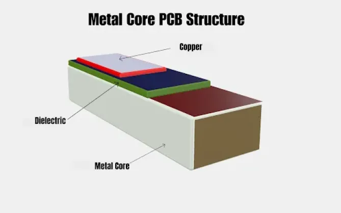
MCPCBs consist of three primary layers: a top copper circuit layer for electrical traces, a central dielectric insulating layer, and a bottom metal core, typically aluminum or copper, for mechanical support and heat spreading. The dielectric serves dual purposes: electrical isolation and thermal conduction pathway. Unlike standard FR4 laminates used in conventional PCBs, MCPCB dielectrics are engineered with thermally conductive fillers, such as ceramics or metal oxides, to bridge the gap between electrical insulation and heat transfer efficiency. Factory processes demand precise control over dielectric application to avoid voids or delamination, which could compromise performance. Understanding these basics helps engineers align material choices with application needs from the outset.
In production, the dielectric is often applied as a prepreg or coated film, cured under controlled pressure and temperature to bond with the metal base. This lamination step, guided by standards like IPC-2221, ensures uniformity in thickness and filler distribution. Variations in material composition affect not just thermal paths but also mechanical integrity under thermal cycling. Engineers benefit from factory-driven insights into how dielectric formulation influences solderability and via reliability in high-power assemblies.
Key Dielectric Properties Affecting Thermal Performance
Thermal Conductivity of the Dielectric
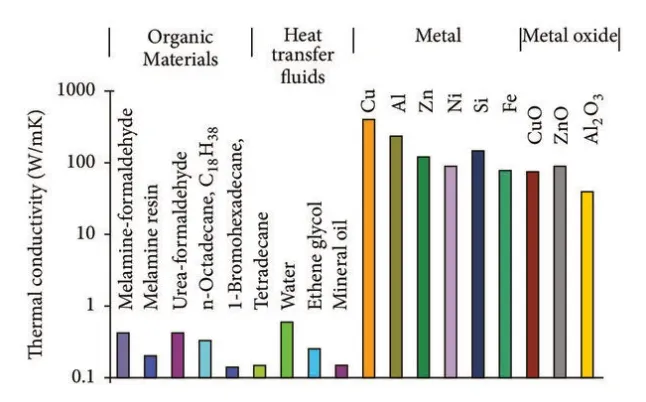
Thermal conductivity dielectric represents the ability of the insulating layer to conduct heat from the copper traces to the metal core. Higher values reduce thermal resistance, allowing faster heat dissipation and lower junction temperatures in power devices. In MCPCBs, this property is enhanced by incorporating conductive particles within a polymer matrix, creating a composite that outperforms standard epoxies. Factory testing verifies this through steady-state or transient methods, ensuring consistency across panels. Engineers prioritize this for applications where component power density exceeds typical FR4 limits.
The interplay between filler loading and matrix compatibility determines achievable conductivity levels. Excessive fillers can increase viscosity during lamination, leading to processing defects, while insufficient amounts limit heat flow. Design simulations model this property alongside copper thickness to predict overall board thermal impedance. Standards like IPC-6012 provide qualification criteria for material performance under load. For guidance on balancing these properties with overall board dimensions, see our guide on How to Choose the Right Thickness for Your Metal Core PCB.
Dielectric Thickness in MCPCBs
Dielectric thickness MCPCB directly governs thermal resistance, as thinner layers shorten the heat transfer path, improving dissipation efficiency. However, excessive thinning risks electrical breakdown or mechanical fragility during handling and assembly. Factory processes balance this by targeting uniform thicknesses via precise coating and etching controls. Thicker dielectrics offer better voltage isolation for high-voltage designs but at the cost of elevated operating temperatures. Engineers model the trade-off using Fourier's law, where resistance scales inversely with thickness.
In multilayer MCPCBs, thickness variations across the panel can create uneven thermal profiles, exacerbating hotspots under load. Production inspections, including cross-section analysis, confirm compliance with tolerances. Optimizing thickness also influences CTE matching with the metal core, minimizing warpage during reflow. This parameter proves essential in sustaining long-term reliability in demanding environments.
High Temperature Dielectric Performance
High temperature dielectric materials maintain structural integrity and insulating properties under elevated thermal loads, crucial for automotive or industrial MCPCBs. These formulations resist degradation, such as softening or charring, which could open conduction paths or increase leakage currents. Factory curing schedules simulate operational stresses to validate stability. Engineers select based on glass transition temperature and decomposition onset, ensuring no phase changes disrupt heat flow.
Thermal aging tests reveal how prolonged exposure affects conductivity and adhesion. In power modules, where peaks exceed standard limits, robust high temperature dielectrics prevent delamination at the copper-dielectric interface. Compliance with JEDEC thermal characterization standards aids in predicting lifespan. This property intertwines with overall board CTE to avoid reliability failures.
Breakdown Voltage of the Dielectric
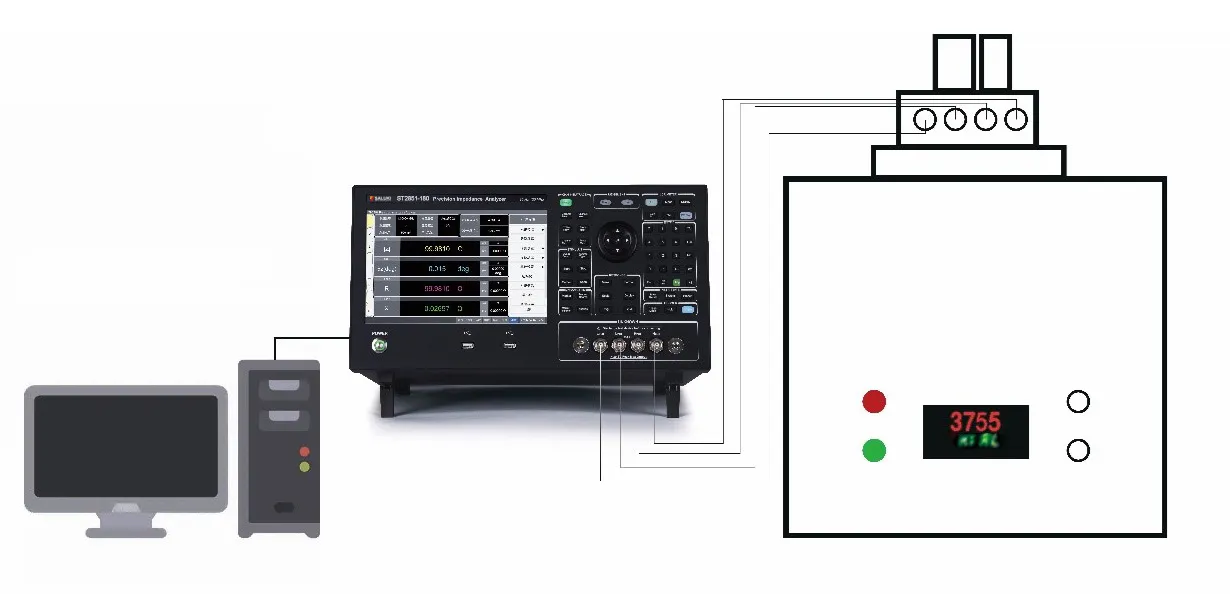
Breakdown voltage dielectric indicates the maximum electric field the material withstands before failure, vital for high-voltage power electronics on MCPCBs. Thinner layers heighten this risk, necessitating higher-strength formulations. Factory dielectric strength tests apply AC or DC voltage ramps to verify isolation between traces and core. Impurities or voids from poor lamination drastically reduce this value, leading to arcing.
Engineers correlate breakdown voltage with thickness and filler type during material qualification. In safety-critical apps, margins exceed operational voltages to account for transients. This property also influences partial discharge inception under humidity. Standards ensure repeatable testing for production consistency.
Heat Transfer Mechanisms in MCPCBs
Heat generated by components flows laterally through copper, vertically through the dielectric, and into the metal core for spreading. The dielectric's low conductivity compared to metals creates a bottleneck, amplifying the need for optimized properties. Conduction dominates, with convection and radiation secondary unless heatsinks are involved. Finite element analysis reveals hotspots where dielectric thickness varies or conductivity dips.
Via thermal resistance adds to the path, as plated barrels compete with dielectric for heat flow. Factory via design minimizes this by favoring filled types in high-power zones. Multilayer configurations complicate paths, requiring symmetric dielectric stacks. Understanding these mechanisms guides iterative design for uniform temperatures.
Standards and Factory Best Practices for Dielectric Selection
IPC-2221 outlines generic design rules for material selection, emphasizing thermal and electrical matching in MCPCBs. Factory workflows incorporate qualification per IPC-6012, testing dielectrics for conductivity, thickness uniformity, and voltage withstand. JEDEC standards like JESD51 series standardize thermal metrics, enabling cross-vendor comparisons.
Best practices include specifying minimum conductivity thresholds early, simulating stackups, and validating prototypes via infrared thermography. Thinner dielectrics suit low-voltage high-heat apps, while thicker ones fit high-voltage needs. Collaborate with fabricators on filler compatibility to avoid lamination defects. Post-lamination inspections catch anomalies before assembly.
Troubleshooting Common Dielectric-Related Thermal Issues
Overheating often traces to inadequate thermal conductivity dielectric, manifesting as junction temps exceeding specs. Warpage from CTE mismatch warps traces, increasing resistance. Factory root-cause analysis uses microscopy for voids. Solutions involve reformulating or adding thermal vias.
High breakdown incidents signal contamination; ramped voltage tests isolate culprits. For high temperature failures, upgrade to ceramics-filled dielectrics. Data logging during burn-in predicts field issues. Learn how these issues manifest during routing in our article on Mastering Metal Core PCB Routing: Tips and Tricks for Optimal Performance.
Conclusion
Dielectric materials profoundly shape MCPCB thermal performance through properties like thermal conductivity, thickness, temperature resilience, and breakdown voltage. Factory-aligned selection per standards ensures reliable heat paths in high-power designs. Engineers gain from balancing trade-offs for optimal dissipation. Prioritizing these in specs yields cooler, longer-lasting boards.
FAQs
Q1: What are the main MCPCB dielectric properties affecting thermal conductivity dielectric?
A1: MCPCB dielectric properties such as filler content and polymer matrix determine thermal conductivity dielectric. Higher conductivity reduces resistance from traces to core. Factory testing confirms values suit power density. Standards guide qualification for consistency.
Q2: How does dielectric thickness MCPCB influence heat dissipation?
A2: Dielectric thickness MCPCB inversely affects thermal resistance; thinner layers enhance transfer but demand voltage checks. Production controls uniformity to avoid hotspots. Simulations predict impacts on junction temps. Balance with isolation needs per design voltage.
Q3: Why is high temperature dielectric critical for MCPCB reliability?
A3: High temperature dielectric prevents degradation in hot environments, maintaining insulation and conduction. It resists softening during peaks from power cycles. Factory aging tests validate. Essential for automotive compliance.
Q4: What role does breakdown voltage dielectric play in MCPCB selection?
A4: Breakdown voltage dielectric ensures safe operation above rated voltages, preventing arcing. Thinner high-conductivity layers lower it, so test rigorously. Factory AC/DC ramps qualify materials. Key for power electronics safety.
References
[1] NextPCB — Metal Core PCB Guide: https://www.nextpcb.com/blog/metal-core-pcb-guide
[2] IPC-2221A — Generic Standard on Printed Board Design. IPC.
[3] IPC-6012E — Qualification and Performance Specification for Rigid Printed Boards. IPC.
[4] JEDEC JESD51-10 — Guidelines for Characterizing Thermal Performance of LED Packages. JEDEC.