Introduction
In high-power applications, effective thermal management is essential to prevent component failure and ensure long-term reliability. Metal core printed circuit boards, commonly known as MCPCBs, address these challenges by incorporating a metal substrate that excels in PCB heat dissipation. Double-sided designs within MCPCBs take this capability further, allowing circuit layers on both sides of the core for optimized routing and heat spreading. Electrical engineers increasingly turn to metal core double-sided PCBs for demanding environments like power electronics and lighting systems. This article explores the principles, design strategies, and manufacturing insights that make these boards a preferred choice for superior thermal performance. By aligning with industry standards, such boards deliver consistent results in thermal management.
What Are Metal Core PCBs and Double-Sided Configurations?
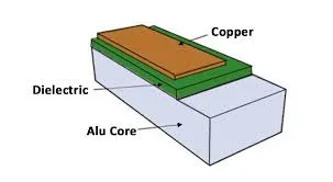
Metal core PCBs feature a solid metal layer, typically aluminum or copper, as the base material instead of traditional FR4 substrates. This core provides a pathway for heat to transfer away from heat-generating components toward external sinks or the board edges. In single-sided MCPCBs, circuitry resides only on the top layer above the dielectric and core, limiting complexity but simplifying fabrication. Double-sided metal core PCBs, however, position copper circuit layers on both the top and bottom surfaces, separated by the metal core and insulating dielectrics. This configuration supports more intricate routing while maintaining excellent thermal conductivity through the core. Such versatility makes metal core double-sided PCBs ideal for applications requiring balanced electrical and thermal performance.
The distinction between single-sided and double-sided lies in interlayer connectivity and heat flow paths. Plated through-holes in double-sided designs must incorporate insulating barriers to prevent shorting to the metal core, ensuring reliable signal transmission. Dielectric materials in these boards prioritize high thermal conductivity alongside electrical isolation, typically exceeding that of standard laminates. Factory processes emphasize precise control over these layers to meet qualification requirements under IPC-6012D for rigid printed boards, including those with metal cores. Engineers benefit from this structure in scenarios where component density increases on both board sides without compromising heat dissipation.
Why Double-Sided MCPCBs Matter for Thermal Management
High-power applications generate substantial heat from components like power transistors and LEDs, which standard PCBs struggle to manage effectively. Poor PCB heat dissipation leads to thermal runaway, reduced lifespan, and performance degradation in compact designs. Metal core double-sided PCBs mitigate these issues by distributing heat across a larger surface area via the conductive core, enabling fanless or compact enclosures. This approach supports higher operating currents and voltages compared to conventional boards, crucial for automotive and industrial systems. Moreover, the mechanical rigidity of the metal core reduces warpage under thermal cycling, enhancing assembly yield and reliability.
In thermal management, the core's role extends beyond conduction to integration with external heatsinks. Double-sided layouts allow heat sources on either side to couple directly to the core, optimizing overall dissipation. This symmetry proves advantageous in symmetric power modules where balanced cooling prevents hotspots. Compliance with design guidelines in IPC-2221 ensures these benefits translate to production-ready boards. Electrical engineers value this for prototyping high-reliability circuits without extensive redesigns.
Technical Principles of Heat Dissipation in Double-Sided MCPCBs
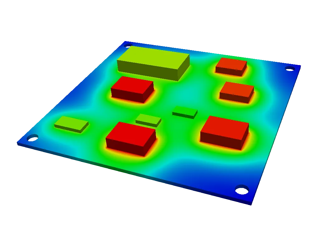
Heat dissipation in metal core double-sided PCBs relies on the high thermal conductivity of the metal core, which rapidly spreads localized heat. Components mounted on either side transfer heat through thin dielectric layers into the core, where it conducts laterally and vertically to sinks. Thermal vias, strategically placed under hot components, bridge circuit layers to the core, bypassing dielectric resistance for direct heat paths. The core's coefficient of thermal expansion closely matches semiconductors, minimizing stress during temperature fluctuations. This multilayer conduction mechanism outperforms FR4 by facilitating uniform temperature distribution across the board.
Dielectric selection is critical, as it must balance electrical insulation with thermal transfer efficiency. Materials engineered for MCPCBs feature optimized filler content to enhance conductivity while maintaining voltage standoff. In double-sided configurations, via design incorporates antipads or insulating plugs to isolate signals from the grounded core, preserving integrity. Factory-driven simulations validate these paths, ensuring hotspots remain below critical thresholds. J-STD-001 guidelines for soldering assemblies further support reliable thermal interfaces on such boards.
Convection and radiation contribute secondarily, amplified by the core's ability to maintain lower surface temperatures. Edge connections to chassis or heatsinks complete the dissipation chain, often via mechanical clips or thermal pads. Engineers model these interactions to predict performance, adjusting trace widths and copper thickness for current handling.
Design Considerations for Optimal Performance
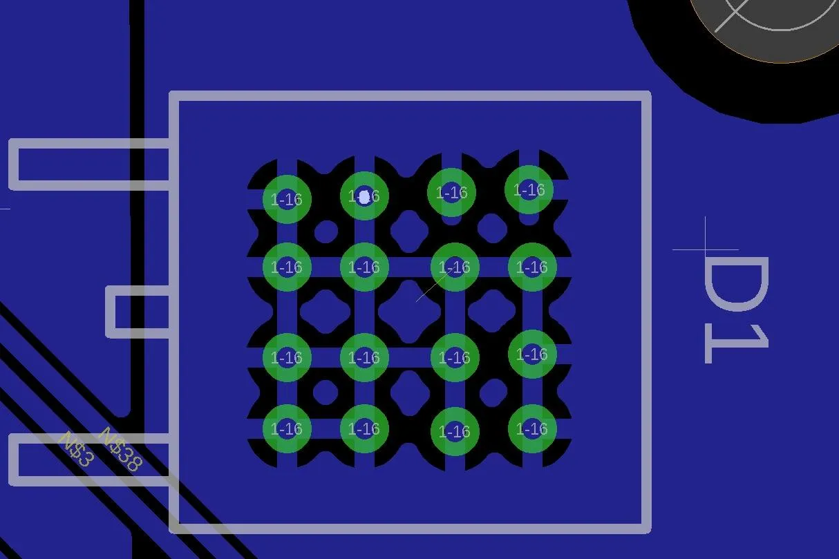
Effective design of metal core double-sided PCBs starts with component placement, positioning high-power devices directly over the core for shortest heat paths. Thermal vias arrays under these components, typically filled or tented, enhance vertical conduction without compromising routing space. Copper pour areas on both sides act as spreaders, connecting to vias for balanced dissipation. Signal integrity demands careful via antipad sizing to avoid capacitance issues with the proximal core. Layer stackup planning ensures dielectric uniformity, preventing uneven heat flow.
Trace routing in double-sided MCPCBs prioritizes wide paths for power lines to minimize resistance and I2R losses. Ground planes on outer layers couple capacitively to the core for shielding and additional heat sinking. Solder mask and silkscreen choices influence surface emissivity for radiation cooling. Prototyping incorporates test points for thermal profiling, guiding iterations. For complementary stack-up techniques, see our guide on metal core PCB stackup design.
Board size and shape impact edge dissipation, with larger areas aiding natural convection. Integration with enclosures requires provisions for heatsink mounting, such as embedded studs in the core. Finite element analysis tools simulate steady-state and transient conditions, aligning designs with application demands.
Manufacturing Processes for Double-Sided MCPCBs
Fabrication of metal core double-sided PCBs begins with core preparation, where the metal sheet receives dielectric coating on both sides followed by copper foil lamination. Precise control of dielectric thickness ensures consistent thermal impedance. Drilling for vias precedes insulating filler application to isolate the core, followed by plating to form interconnects. Etching defines circuitry on both surfaces, with alignment critical for multilayer registration.
Multistep pressing bonds layers under controlled pressure and temperature, avoiding core distortion. Surface finishes like ENIG or HASL provide solderable thermal interfaces compliant with assembly standards. Electrical testing verifies continuity and shorts, while thermal shock tests assess integrity per IPC specifications. Yield optimization focuses on via reliability in high-density zones.
Post-processing includes routing and scoring for panelization, with edge beveling to facilitate heatsink contact. Quality checks employ automated optical inspection for defects in dielectric coverage. These designs position double-sided MCPCBs as a key solution for high-power metal core PCBs.
Applications in High-Power Scenarios
Metal core double-sided PCBs excel in power supplies, where inverters and converters demand robust thermal management. Automotive electronics, including motor drives, leverage their durability under vibration and heat. LED lighting arrays benefit from uniform dissipation, extending module life. RF amplifiers and telecom gear use them for handling pulsed power without derating.
In renewable energy inverters, these boards manage grid-tie heat loads efficiently. Defense systems prioritize their compactness and reliability.
Best Practices for Implementation
Select core thickness based on power density, balancing rigidity and weight. Simulate thermal profiles early, iterating via placement iteratively. Specify dielectric thermal conductivity explicitly in documentation. Validate prototypes with infrared thermography. Partner with fabricators experienced in MCPCB processes for first-pass success.
Conclusion
Double-sided metal core PCBs represent a proven advancement in thermal management for high-power applications. Their layered architecture enables superior PCB heat dissipation through efficient core conduction and via integration. Design and manufacturing aligned with standards ensure reliability. Electrical engineers can confidently deploy these boards to meet demanding thermal requirements, enhancing overall system performance.
FAQs
Q1: What advantages do metal core double-sided PCBs offer over standard FR4 in thermal management?
A1: Metal core double-sided PCBs provide significantly better heat spreading via the conductive core, supporting higher power densities without excessive temperatures. This reduces reliance on active cooling in compact designs. Factory processes ensure dielectric integrity for reliable heat paths. Ideal for high-power applications, they extend component life through uniform dissipation.
Q2: How do thermal vias improve PCB heat dissipation in MCPCBs?
A2: Thermal vias connect circuit layers directly to the metal core, minimizing thermal resistance from dielectrics. Arrays under components distribute heat effectively in double-sided configurations. Proper sizing and filling prevent solder wicking issues during assembly. This enhances overall thermal management per design standards.
Q3: What design challenges arise with metal core double-sided PCBs?
A3: Via isolation from the core requires precise antipads to avoid shorts, complicating routing. Dielectric selection must balance conductivity and insulation. Mechanical stresses demand warpage controls. Simulations and standards compliance mitigate these for production viability.
Q4: Are MCPCBs suitable for all high-power applications?
A4: MCPCBs shine in scenarios prioritizing passive thermal management, like LED drivers and power modules. Double-sided variants suit balanced layouts. However, extreme densities may need hybrids. Evaluate based on power levels and enclosure constraints.
References
IPC-6012D — Qualification and Performance Specification for Rigid Printed Boards. IPC, 2015
IPC-2221B — Generic Standard on Printed Board Design. IPC, 2012
J-STD-001H — Requirements for Soldered Electrical and Electronic Assemblies. IPC/JEDEC, 2018