Introduction
Flexible electronics open up exciting possibilities for electronic hobbyists who want to build compact, innovative projects that traditional rigid boards cannot handle. Semi-flex PCBs represent a practical middle ground, combining the stability of rigid sections with the bendability of flexible areas. These boards are ideal for DIY enthusiasts experimenting with wearables, foldable gadgets, or space-constrained prototypes. As a semi-flex PCB hobbyist, you gain the freedom to create devices that adapt to real-world shapes without sacrificing reliability. This guide breaks down everything from basics to hands-on tips, helping you dive into semi-flex PCB DIY projects with confidence. Whether you are prototyping your first bendable circuit or refining a complex idea, understanding semi-flex PCBs will elevate your hobbyist toolkit.
What Are Semi-Flex PCBs and Why They Matter for Hobbyists
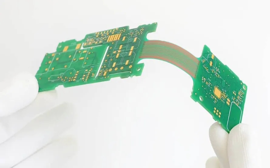
Semi-flex PCBs feature a hybrid construction with rigid portions made from standard substrates like FR4 and flexible sections using materials such as polyimide. This design allows the board to bend in specific zones while maintaining structural integrity elsewhere, making it perfect for applications where full rigidity or complete flexibility falls short. For hobbyists, semi-flex PCBs matter because they enable creative project ideas that fit irregular forms, like curved enclosures or wearable tech. Unlike pure flex boards, which can be tricky to handle during assembly, semi-flex options provide familiar rigid areas for mounting components. They reduce mechanical stress in dynamic environments, extending the life of your DIY builds. In short, semi-flex PCB hobbyists find these boards versatile for everything from robotics arms to portable sensors.
The relevance grows as hobby projects demand smaller footprints and adaptability. Traditional rigid PCBs limit designs to flat layouts, but semi-flex boards allow folding or twisting without breaks in connectivity. This capability supports semi-flex PCB project ideas such as health-monitoring bands or drone payloads that conform to shapes. Hobbyists appreciate the cost-effectiveness too, as semi-flex construction avoids the premium pricing of full rigid-flex without overcomplicating simple bends. Standards like IPC-6013 ensure these boards meet performance benchmarks for flexibility and durability, giving you peace of mind in your builds.

Technical Principles Behind Semi-Flex PCBs
Semi-flex PCBs rely on layered construction where rigid multilayers integrate with single or double-sided flexible tails. The flexible areas use thin copper traces on polyimide film, which withstands repeated bending due to its ductility. Rigid sections provide mounting platforms for through-hole or surface-mount components, anchored by vias that transition smoothly to flex zones. This integration prevents delamination by controlling material thickness and adhesion, typically achieved through controlled lamination processes. Engineers design bend radii carefully to avoid trace cracking, often specifying minimum bend cycles based on copper weight and substrate properties.
Key to reliability is the copper patterning in flex regions, where traces are etched wider or reinforced to handle strain. Coverlays protect these traces, similar to solder masks on rigid boards, but formulated for flexibility. The overall stackup balances stiffness gradients, ensuring the board folds predictably without warping. Adherence to IPC standards governs these aspects, specifying qualification tests for flex endurance and interlayer bonds. For hobbyists, grasping these principles means selecting appropriate designs that match your project's mechanical demands. Visualizing the stackup helps in planning traces that route through transition zones without sharp angles.
Thermal management also plays a role, as flex materials have different coefficients of thermal expansion compared to rigid ones. During operation, components on rigid areas generate heat that must dissipate without stressing flex joints. Hobbyists can mitigate this by spacing heat sources away from bends and using thermal vias. These technical foundations make semi-flex PCBs robust for dynamic hobby applications.
Practical Solutions and Best Practices for Semi-Flex PCB Prototyping
Starting with semi-flex PCB prototyping begins with defining your project's bend requirements and rigid mount points. Sketch the layout on paper first, marking flex zones and ensuring traces in those areas follow gentle curves with adequate spacing. Use free design tools to generate Gerber files, specifying stackups with rigid cores and flex extensions. When ordering prototypes, communicate panelization needs clearly to fit multiple small boards efficiently. Opt for 1-2 layer flex sections initially to keep costs low and simplify iteration. Testing prototypes involves manual flex cycles to verify no cracks form, gradually increasing bend angles.
For semi-flex PCB DIY workflows, iterate designs based on physical mockups using tape and foil to simulate flex behavior. Incorporate stiffeners on rigid areas if needed for component stability during handling. Prototyping small runs allows quick feedback on issues like trace impedance in flex tails. Always review the fabricator's capabilities for controlled impedance if signals demand it. This hands-on approach builds intuition for future semi-flex PCB project ideas.
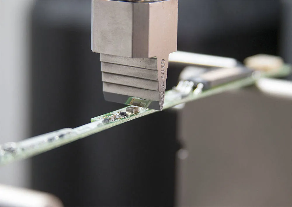
Assembly best practices focus on fixturing to hold flex sections flat during soldering. Use low-temperature solders for polyimide to prevent shrinkage, preheating boards gently. For semi-flex PCB soldering, tack down components on rigid areas first, then align flex tails before final reflow. Avoid excessive flux on flex surfaces to minimize residue that could promote cracking over time. J-STD-001 guidelines outline soldering parameters, emphasizing clean joints in transition zones. Post-assembly, apply conformal coatings selectively to protect flex areas from environmental exposure.
Semi-Flex PCB Project Ideas and Hands-On DIY Tips
Hobbyists can explore semi-flex PCB project ideas like a foldable LED matrix for portable displays. Mount LEDs and drivers on the rigid center, with flex tails connecting to battery holders that tuck away when folded. This setup saves space in pockets or bags, ideal for on-the-go demos. Another idea is a wearable gesture sensor band, where flex sections wrap around the wrist while the microcontroller sits rigidly. Route sensor traces through flex for natural contouring, enabling comfortable all-day wear.
For robotics enthusiasts, build a semi-flex PCB DIY gripper arm with flex joints for multi-axis movement. Rigid platforms hold motors, flex links transmit signals without cabling snags. Test durability by simulating repeated grasps, refining trace widths for reliability. A compact drone camera gimbal uses semi-flex to isolate vibrations, with rigid mounts for the camera and flex for shock absorption. These projects highlight how semi-flex boards enable creative freedom.
Advanced hobbyists might prototype a semi-flex PCB for a smart plant monitor that conforms to pot curves. Flex tails extend probes into soil while the main board stays elevated. Integrate moisture sensors and LEDs, powering via flexible battery contacts. Such ideas scale from simple prototypes to functional gadgets, fostering experimentation.
Troubleshooting Common Challenges in Semi-Flex Builds
Flex tails may lift during soldering if not secured properly, so use temporary clamps or adhesive dots. Trace cracks in high-bend areas often stem from tight radii; redesign with fillets and increase copper thickness. Warpage in rigid-flex transitions occurs from mismatched CTEs, addressed by symmetric stackups. Inspect under magnification post-flex for micro-cracks, cycling boards 100 times minimally. If signals degrade, check for impedance mismatches at transitions. These fixes ensure robust semi-flex PCB hobbyist outcomes.
Conclusion
Semi-flex PCBs empower hobbyists to push beyond flat designs into truly adaptable electronics. From understanding hybrid construction to mastering prototyping and soldering, these boards unlock innovative project ideas. Key practices like gentle bends, proper fixturing, and standard adherence yield reliable results. Whether DIY wearables or robotic links, semi-flex options fit diverse needs. Start small, prototype iteratively, and watch your creations bend to your vision. Embrace flexible PCB application possibilities in wearables, compact robotics, consumer electronics, and DIY smart devices, where mechanical adaptability and space-saving layouts are essential.
FAQs
Q1: What makes semi-flex PCBs suitable for hobbyist projects?
A1: Semi-flex PCBs combine rigid stability with flexible sections, ideal for semi-flex PCB project ideas like wearables or foldables. They handle moderate bending without full flex complexity, suiting DIY budgets and skills. Standards ensure durability, while prototyping focuses on simple stackups for quick iterations.
Q2: How do I approach semi-flex PCB prototyping as a beginner?
A2: Begin with layout sketches defining flex zones, generate Gerbers for small panels. Order prototypes specifying bend radii and test manually. Use symmetric designs to avoid warpage, iterating based on flex cycles. This semi-flex PCB prototyping method builds confidence for complex builds.
Q3: What are best practices for semi-flex PCB soldering?
A3: Secure flex tails flat with fixturing, use low-temp profiles per J-STD-001. Solder rigid areas first, inspect transitions closely. Minimize flux on flex to prevent residue issues. These steps ensure clean, reliable semi-flex PCB soldering joints.
Q4: Can I try semi-flex PCB DIY without advanced tools?
A4: Yes, start with basic hand tools for tacking components, progressing to reflow ovens. Mockups with foil simulate bends pre-prototype. Focus on wide traces and gentle curves for durability in semi-flex PCB DIY projects.
References
IPC-6013D — Qualification and Performance Specification for Flexible and Rigid-Flex Printed Boards. IPC, 2014
J-STD-001H — Requirements for Soldered Electrical and Electronic Assemblies. IPC, 2018