 00:57
00:57
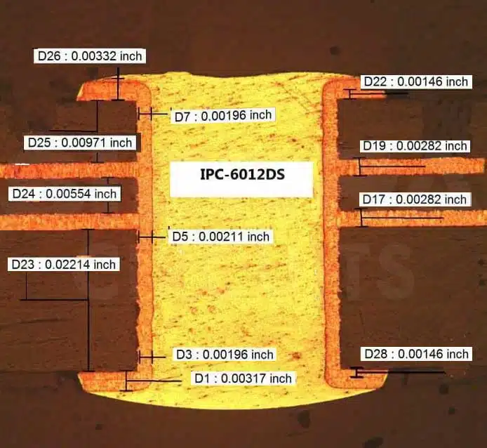
Drill Size
Understanding drill size is fundamental to successful printed circuit board (PCB) design and manufacturing, as it directly influences the precision of holes for components, vias, and mounting. In electronics, drill size refers to the diameter of the holes drilled into a PCB substrate, typically measured in millimeters or inches, and it must align with component leads, trace routing, and overall board integrity. For engineers and hobbyists searching for information on drill size, this tag compiles resources that explain how to select appropriate sizes to avoid issues like signal interference, mechanical weakness, or assembly failures. Common drill sizes range from 0.2mm for fine-pitch vias to larger diameters like 3mm for connectors, and choosing the right one ensures reliable electrical connections and structural stability. Practical applications of proper drill size selection extend to both prototyping and high-volume production. For instance, in PCB fabrication, using a drill size that matches the pad annulus prevents shorts or opens, while accounting for plating thickness can optimize hole tolerances. Best practices include consulting manufacturer datasheets for component specifications, employing CNC drilling for accuracy, and testing prototypes with calipers to verify dimensions. This approach minimizes rework and enhances yield rates, which is crucial for time-sensitive projects. Articles under this tag offer detailed guides on calculating drill sizes based on IPC standards, troubleshooting common drilling errors, and integrating drill size considerations into CAD software like Eagle or KiCad. By delving into these topics, readers can gain actionable insights to refine their PCB workflows. Whether you are optimizing a design for manufacturability or addressing drill-related defects in existing boards, the content here provides the technical depth needed to make informed decisions and improve outcomes in electronics projects.
Video Guide
-
00:57
Technical Articles
Get in Touch
Send Message
- Products & Service
- Company
- About AIVON
- Contact
- News
- Blog
- Certification
-


- Payment
-


2026 AIVON.COM All Rights Reserved