 00:54
00:54
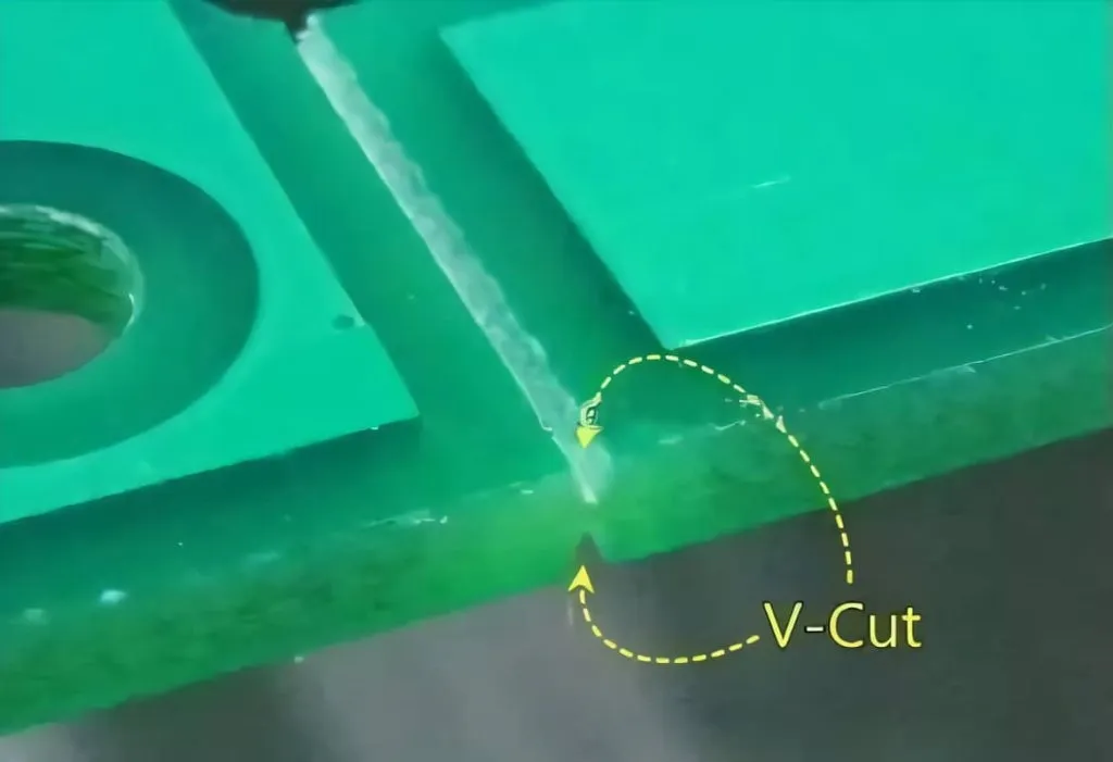
V-Cut
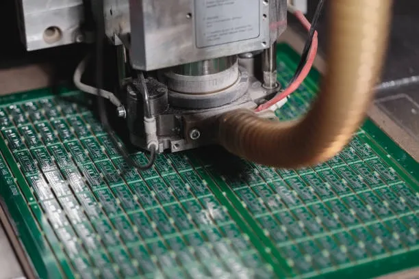
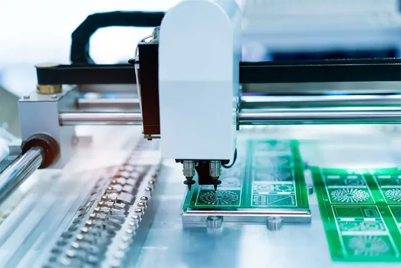
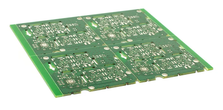
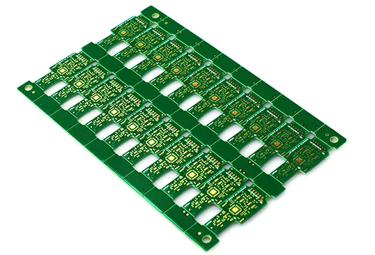
V-Cut, also known as V-groove scoring, is a precise method used in printed circuit board (PCB) manufacturing to facilitate the separation of individual boards from larger panels. This technique involves cutting shallow V-shaped grooves along the edges where boards will be broken apart, ensuring clean breaks without damaging components or traces. For engineers, designers, and manufacturers searching for information on V-Cut, this tag serves as a centralized resource covering its implementation, advantages, and potential challenges in modern electronics production. In practical terms, V-Cut enhances efficiency in high-volume PCB assembly by allowing panels to be processed as a single unit during soldering, testing, and inspection, then easily depaneled afterward. This approach minimizes handling time and reduces the risk of defects compared to other methods like routing or milling. For instance, in applications such as consumer electronics, automotive systems, or IoT devices, incorporating V-Cut can streamline production workflows and improve yield rates. Users often seek guidance on parameters like groove depth, angle (typically 30 to 45 degrees), and material compatibility, which are critical for avoiding issues such as board warping or incomplete separation. To achieve optimal results, best practices include designing with sufficient border space around V-Cut lines and selecting appropriate PCB thicknesses, usually between 0.6mm and 2.5mm, to ensure structural integrity. It's also advisable to simulate stress points during the design phase using CAD software to prevent fractures in sensitive areas. The articles grouped under this V-Cut tag delve into these topics with real-world examples, troubleshooting tips, and case studies, helping you refine your PCB designs and manufacturing processes effectively.
Video Guide
-
00:54
Technical Articles
Depanelization Techniques: Stamp Holes vs. V-Scoring for PCBs
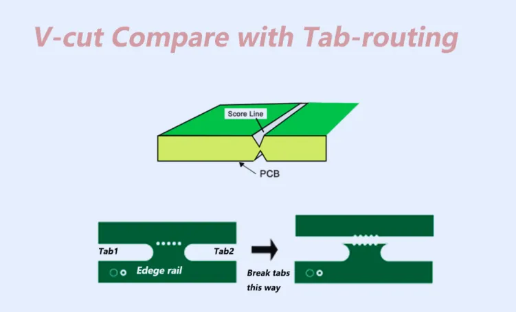
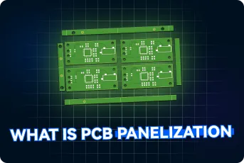
PCB Panelization: V-Cut vs. Tab-Routing for Efficient Manufacturing
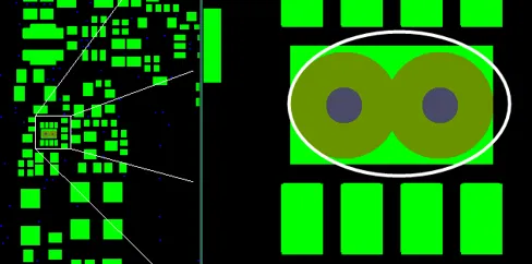
8-Layer FR-4 PCB with Blind Vias: Solder Mask Openings, Via Plugging and V-CUT Clearance Issues During CAM Review
Choosing the Right PCB Depaneling Method: A Comprehensive Comparison
Mastering PCB Depaneling: A Step by Step Tutorial
Making the Cut: Choosing the right PCB depaneling Method
V-Scoring vs. Routing: Selecting the Optimal PCB Depaneling Method
Get in Touch
Send Message
- Products & Service
- Company
- About AIVON
- Contact
- News
- Blog
- Certification
-


- Payment
-


2026 AIVON.COM All Rights Reserved