










-
 00:45
00:45
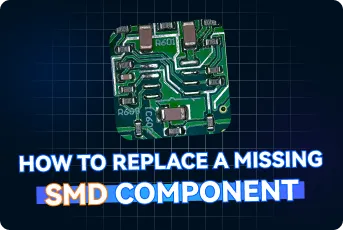
Missing SMD Component Replacement: Step-by-Step Hot-Air PCB Repair
Replacing a missing SMD component is a common PCB rework task that requires precision to restore circuit functionality without damaging the board. This video demonstrates a proven repair process, from identifying the correct component value, package, and polarity to applying flux, accurately positioning the part, and using controlled hot-air reflow to create reliable solder joints. It also covers post-rework cleaning and visual inspection to verify assembly quality. By following these best practices, engineers and technicians can reduce rework costs, improve repair success rates, and maintain the reliability of rigid, multilayer, and HDI PCB assemblies used in automotive, industrial, consumer, and other demanding electronic applications.
-
 00:46
00:46
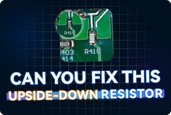
How to Repair an Upside-Down SMD Resistor on PCB
Correcting an incorrectly oriented SMD resistor is a common PCB rework task that requires precision to avoid damaging the board or surrounding components. This video demonstrates a proven repair process, including safe component removal with controlled hot air, proper flux application, accurate repositioning, and even reflow soldering to create reliable joints. It also covers post-rework cleaning and visual inspection techniques used to verify solder joint quality and board integrity. By following these best practices, engineers and technicians can restore electrical performance, improve assembly yield, and maintain the reliability of prototype and production PCB assemblies used in industrial, consumer, and other high-performance electronic applications.
-
 00:46
00:46
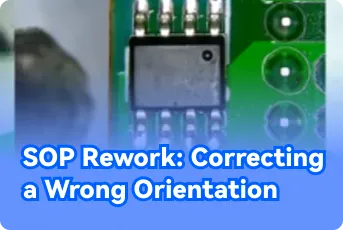
SOP Rework for Correcting Wrong Chip Orientation on PCBs
Incorrectly oriented SOP (Small Outline Package) components are a common SMT assembly error that can cause immediate circuit failure despite otherwise perfect solder joints. This video demonstrates the complete rework process for safely removing, cleaning, realigning, and resoldering an SOP chip with the correct Pin 1 orientation. It highlights essential techniques such as controlled hot-air heating, pad cleaning, flux application, precise component alignment, and careful reflow to produce reliable solder joints while minimizing the risk of pad or trace damage. By following these best practices, engineers and technicians can reduce rework, improve assembly quality, and maintain the reliability of multilayer, HDI, and rigid-flex PCB assemblies used in medical, automotive, industrial, and other high-performance applications.
-
 00:45
00:45
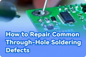
How to Repair Common Through-Hole Soldering Defects
Through-hole soldering defects such as solder bridges, insufficient solder, and solder spikes can significantly affect the reliability of PCB assemblies. This video demonstrates professional repair techniques for correcting these common issues while preserving component and board integrity. It covers essential soldering practices, including proper heat application, solder feeding, and iron removal techniques to produce strong, smooth solder joints that meet industry standards. By mastering these methods, engineers and technicians can improve first-pass yield, reduce rework, and enhance the long-term reliability of FR4, flexible, rigid-flex, and other high-performance PCB assemblies used in automotive, medical, and industrial applications.
-
 00:48
00:48
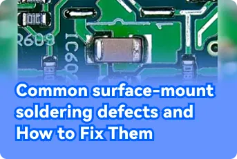
Common SMD Soldering Defects and Reliable Repair Methods for SMT Assemblies
SMD soldering defects such as misaligned components and cold joints are common issues in PCB rework that can affect both electrical performance and mechanical reliability. This video demonstrates a structured repair process, including safe component removal with hot air, thorough pad cleaning, flux application, precise placement of new components, and proper reflow soldering. It also highlights the importance of post-repair cleaning and inspection to ensure joint quality and consistency. By applying these techniques, engineers and technicians can improve rework efficiency, restore board functionality, and maintain reliability in HDI, medical, automotive, and industrial PCB applications.


