Multilayer FR4 PCB Manufacturing Challenges and Common CAM EQs
Multilayer FR4 PCBs (4 layers and above) form the foundation of the majority of complex electronic products today. They provide the necessary routing density, power distribution, and signal integrity for applications ranging from networking equipment and industrial automation to automotive electronics and medical instruments. Compared to 2-layer boards, multilayer constructions introduce significantly more variables during manufacturing, particularly in the areas of lamination, registration accuracy, and copper balance across multiple layers.
In actual engineering file reviews and CAM processing at AIVON, multilayer FR4 boards consistently generate a high volume of Engineering Queries (EQs). The most frequent issues revolve around stack-up configuration, impedance control, inner layer features, via treatment, and mechanical clearance. These problems arise because designers often apply rules developed for simpler boards without fully accounting for the cumulative effects of multiple lamination cycles, material behavior under pressure, and tight process tolerances required for reliable multilayer production.
This article consolidates the most common real-world EQs observed across thousands of multilayer FR4 orders. Every example is drawn directly from CAM templates and factory experience. The goal is to help engineers identify potential issues during the design phase, reduce unnecessary back-and-forth communication, improve first-pass yield, and shorten overall lead time.
Case 1: Stack-up and Layer Sequence Confirmation in Multilayer FR4 Boards
Case Overview
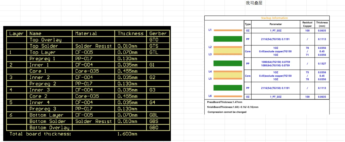
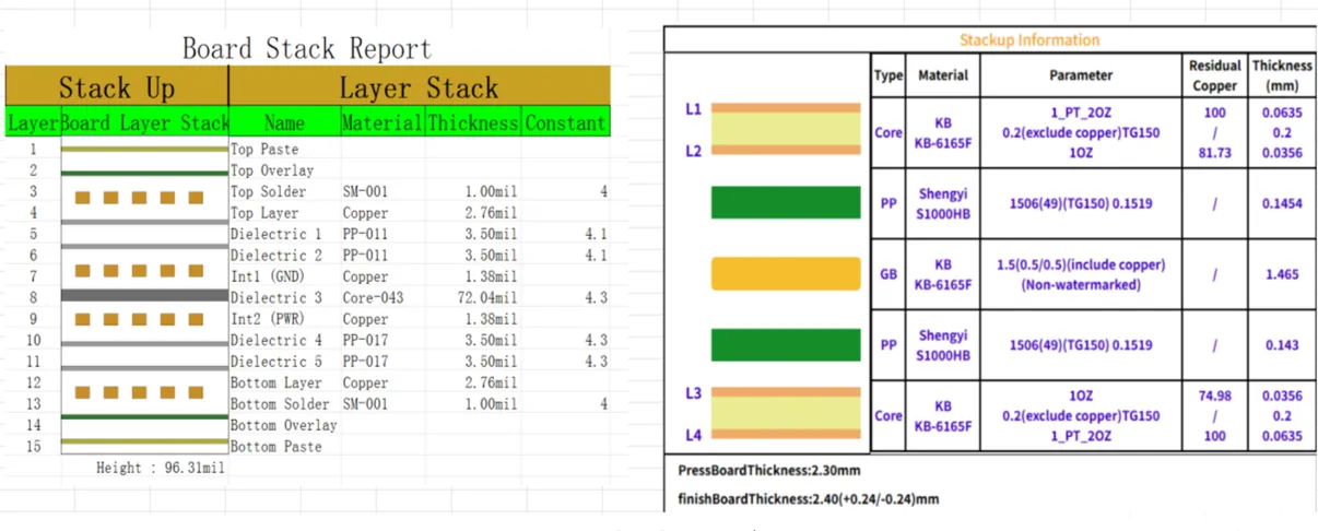
Customers frequently submit initial stack-up drawings for multilayer FR4 boards that do not perfectly align with available core and prepreg materials or standard press parameters. This is particularly common in 4-layer, 6-layer, and 8-layer PCB designs where outer layer copper thickness and dielectric spacing play a critical role in final electrical performance.
Engineering Observation
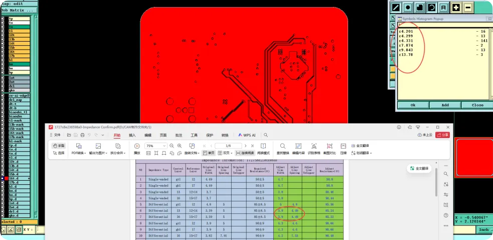
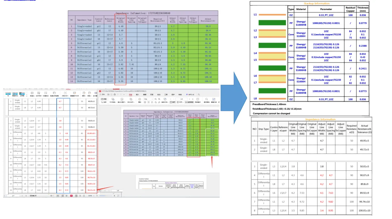
During layer press confirmation, the proposed factory stack-up shows clear differences from the customer’s requested configuration, especially regarding outer layer base copper thickness and overall board thickness tolerance.
Root Cause Analysis
Material inventory limitations and the physics of lamination (pressure, temperature, and resin flow) often require minor adjustments to the ideal stack-up. Outer layer copper thickness in the design files usually refers to base copper before plating, which many designers do not fully consider.
Design Impact
Unconfirmed or mismatched stack-up directly leads to impedance deviation, layer-to-layer registration errors, board warpage, and potential failure to meet the original electrical or mechanical specifications.
Recommended Solution
Please kindly check whether the adjusted stack-up and impedance control is ok for you or not. We will use standard base copper thickness for outer layers unless otherwise specified.
Engineering Takeaway
Always review and formally approve the final factory stack-up drawing as early as possible in multilayer FR4 projects. Early confirmation prevents downstream impedance deviations and registration problems that are difficult and expensive to correct later.
| Factor | Common Issue | Impact |
|---|---|---|
| Outer Layer Copper | Base vs finished thickness | Impedance deviation |
| Dielectric Spacing | Mismatch with inventory | Warpage and registration errors |
Table 1: Common Multilayer FR4 Stack-up EQ Factors
Case 2: Impedance Control Requirements and Reference Layers
Case Overview
High-speed signals in multilayer FR4 designs require controlled impedance, yet many files lack explicit target values, reference layer definitions, or shielding requirements.
Engineering Observation
DFM review frequently identifies impedance-controlled traces that do not have continuous reference planes or proper shielding on adjacent layers.
Root Cause Analysis
Designers sometimes assume impedance will be automatically achieved or rely on default calculations without providing specific single-ended (typically 50Ω) or differential (90/100Ω) targets and ensuring dedicated reference layers throughout the stack-up.
Design Impact
Deviated or uncontrolled impedance results in signal integrity problems, increased EMI, timing issues, and potential board respins that can delay the entire project by weeks.
Recommended Solution
Please advise whether we should perform impedance control for the highlighted lines and provide the exact target values. If adjustment is needed to meet the requirement, we will modify trace width and spacing accordingly.
Engineering Takeaway
For all multilayer FR4 designs with high-speed signals, always specify exact impedance targets and ensure continuous, dedicated reference layers for every controlled trace. This single practice eliminates one of the most costly and time-consuming EQs.
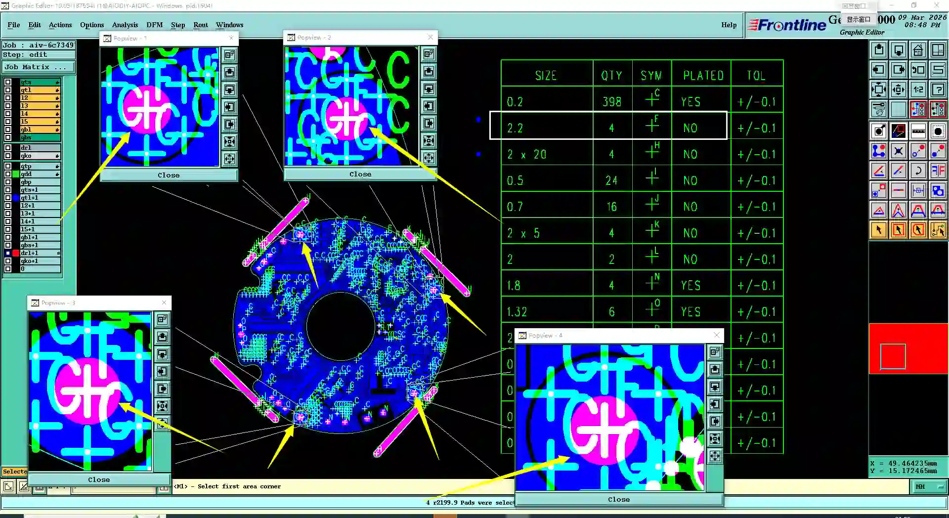
Case 3: Inner Layer Copper Balance and Isolated Pad Management
Case Overview
Inner layers in multilayer FR4 boards commonly contain isolated pads or unbalanced copper distribution that can cause significant manufacturing challenges.
Engineering Observation
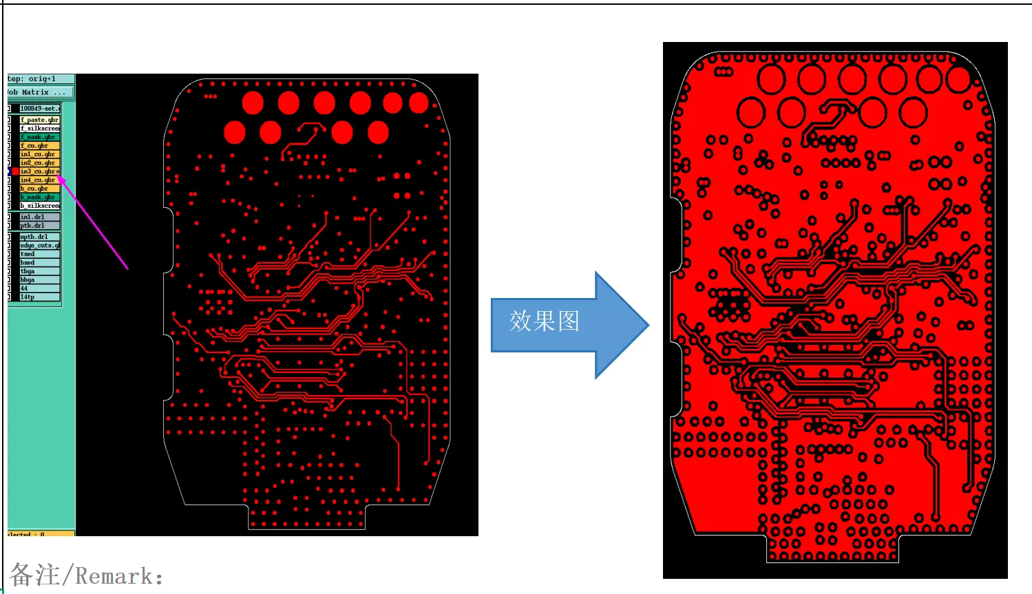
CAM review identifies numerous isolated pads on inner layers or noticeable copper density imbalance between different layers.
Root Cause Analysis
Designers often leave floating or isolated pads from schematic cleanup or copy-paste operations, and fail to balance copper area across layers, which becomes critical as layer count increases.
Design Impact
Unbalanced copper distribution leads to board warpage, layer misalignment during lamination, etching difficulties, and reduced long-term reliability under thermal cycling.
Recommended Solution
Inner layer isolated pads: please advise whether we can delete them to facilitate fabrication or retain them as designed.
Engineering Takeaway
Minimize unnecessary isolated pads and strive for symmetrical copper balance across all layers in multilayer FR4 designs. This directly controls warpage and improves overall manufacturing yield.
Case 4: Via Tenting Specifications vs Solder Mask Layer Consistency
Case Overview
Multilayer FR4 designs frequently specify via tenting or covering on the quote while the actual solder mask layers in Gerber files show conflicting configurations.
Engineering Observation
Quote selection indicates tenting, but files show vias not covered (or the reverse situation).
Root Cause Analysis
The discrepancy typically occurs when designers change the finish or via treatment late in the design process without updating the corresponding solder mask layers.
Design Impact
Incorrect via treatment can allow solder mask ink to enter holes (causing blockages) or leave vias exposed, leading to solder wicking, shorts, or assembly defects.
Recommended Solution
You chose Vias Tenting on the instant quote page, but in your file it is Vias Not Covered. Please advise: 1. do as chosen (Tenting) or 2. do as per file.
Engineering Takeaway
Always keep via tenting or covering specifications consistent between the quote selection and the actual solder mask layers in Gerber files for multilayer FR4 boards.
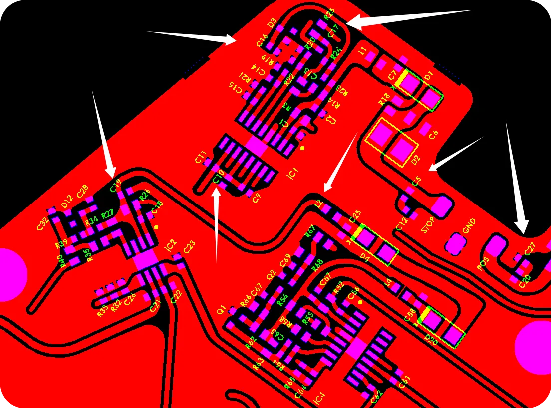
Case 5: Board Edge Clearance and Outline Definition for Reliable Routing
Case Overview
Pads and traces placed too close to the board edge or using wide, ambiguous outline lines in multilayer FR4 files.
Engineering Observation
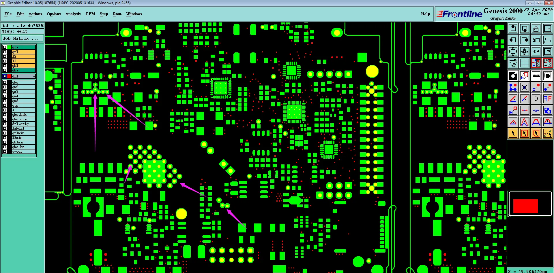
DFM analysis shows critical features within unsafe distance of the routed or V-cut edge, or thick outline lines that make final dimension unclear.
Root Cause Analysis
Designers maximize usable area without fully considering multilayer mechanical processing tolerances and the cumulative stress from multiple lamination steps.
Design Impact
Routing or V-cutting can cause exposed copper, burrs, lifted pads, or damaged traces, affecting both cosmetic quality and electrical performance.
Recommended Solution
Pad/trace distance to board edge is too close or outline line is too wide. Please advise whether you accept the risk or require design revision.
Engineering Takeaway
Maintain safe clearance (minimum 0.2mm for routed edges, 0.4mm for V-cut) and clearly define final board dimensions when using thick outline lines in multilayer FR4 designs.
DFM Strategies to Reduce Engineering Queries in Multilayer FR4 Production
- Provide a complete, clearly labeled stack-up drawing with exact impedance targets and reference layers as early as possible.
- Aim for symmetrical copper distribution across all layers to control warpage and registration.
- Keep via tenting/covering specifications consistent between quote and solder mask layers.
- Maintain adequate edge clearance and explicitly define outline dimensions.
- Minimize or clearly document isolated inner-layer pads.
- Clearly specify PTH vs NPTH attributes for every hole type.
- Upload files early for a free DFM review — this single step catches the majority of multilayer EQs before production starts.
- Consult our Multilayer FR4 Manufacturing Insights page for detailed capability limits and recommended design rules.
| Factor | Common Issue | Impact |
|---|---|---|
| Outer Layer Copper | Base vs finished thickness | Impedance deviation |
| Dielectric Spacing | Mismatch with inventory | Warpage and registration errors |
Table 2: Common Multilayer FR4 Stack-up EQ Factors
Conclusion
Multilayer FR4 PCBs deliver excellent performance and cost-effectiveness when design intent is properly aligned with manufacturing reality. By proactively addressing the common EQs related to stack-up, impedance, copper balance, via treatment, and mechanical clearance, engineers can dramatically reduce engineering clarifications, improve yield, and shorten time-to-market. The key is early communication and adherence to proven design rules derived from real factory experience.
For tangible proof of stable multilayer FR4 delivery, explore our Production Records. Ready to move forward with your multilayer project? Get a Quote today or upload your files for a comprehensive, no-obligation engineering review.
FAQs
Q1: When should stack-up be confirmed for multilayer FR4 boards?
A1: As early as possible in the design cycle. Factory adjustments for material availability are common and best resolved before final Gerber release.
Q2: How do I prevent warpage in multilayer FR4 designs?
A2: Achieve symmetrical copper distribution across layers and minimize isolated inner-layer pads. Copper balance is one of the most effective warpage controls.
Q3: Is via tenting required for all multilayer FR4 boards?
A3: It depends on your design intent and assembly requirements. The critical point is consistency between quote selection and solder mask layers.
Q4: What is the most common cause of EQ in multilayer FR4 production?
A4: Mismatch between quote parameters (especially stack-up and impedance) and actual Gerber files. Double-checking this alignment prevents most issues.
Q5: What files should I prepare before submitting a multilayer FR4 order?
A5: Complete Gerber set, detailed stack-up drawing with impedance targets, clear hole attributes, and balanced copper distribution. Early DFM review is strongly recommended.
References
IPC-6012E — Qualification and Performance Specification for Rigid Printed Boards.