Introduction
Robotics projects captivate electronic hobbyists with the promise of creating machines that can sense, move, and interact with their environment. At the heart of every robot lies a robotics PCB, serving as the central hub for robotics electronics. These boards integrate microcontrollers, motor control circuits, and sensor integration to bring a robot to life. Designing and assembling a robotics PCB can seem daunting, but with a structured approach, hobbyists can achieve reliable and efficient results. This guide offers practical insights into crafting microcontroller PCBs tailored for robotics, covering essential robotics pcb design principles and robotics pcb assembly techniques. Whether you're building a simple line-following robot or a complex autonomous system, understanding robotics pcb assembly for robots is key to success. Let's explore the steps to design and build a PCB that powers your robotics vision.
The Critical Role of Robotics PCBs in Robot Performance and Hobbyist Innovation
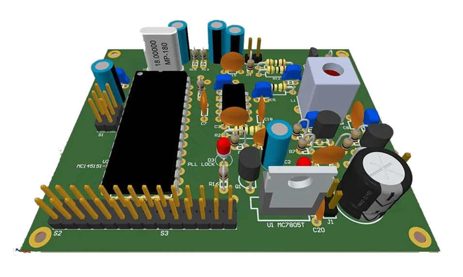
A robotics PCB is a specialized circuit board designed to manage the electronic components of a robot. It acts as the backbone, connecting microcontrollers, sensors, actuators, and power systems to ensure seamless operation. These boards are critical in robotics electronics because they provide the electrical infrastructure for processing data, controlling movements, and responding to environmental inputs. Without a well-designed robotics PCB, a robot may suffer from unreliable performance, signal interference, or power inefficiencies.
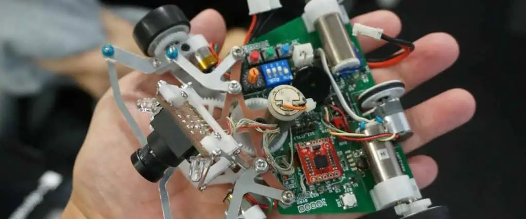
For electronic hobbyists, the importance of a robotics PCB lies in its ability to consolidate complex circuits into a compact, organized layout. A thoughtfully engineered PCB reduces wiring clutter, minimizes errors, and enhances the durability of the robot. By focusing on motor control circuits and sensor integration, hobbyists can create systems that execute precise tasks, from navigating obstacles to manipulating objects. Mastering robotics pcb design opens doors to innovative projects and deeper learning in electronics.
Common Types of PCBs Used in Robotic Automation and Their Applications
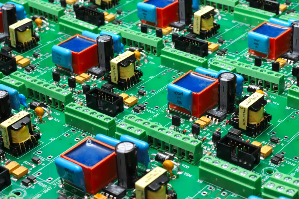
Different PCB types suit varying robotics needs, balancing cost, complexity, and performance in robotics pcb design.
Single-Sided PCB
These basic boards have copper on one side only, making them inexpensive and simple to manufacture. They are ideal for entry-level robots like line-followers or basic obstacle avoiders, where space is limited and only a few components (e.g., one microcontroller and basic sensors) are required. Limitations include restricted routing and lower component density.
Double-Sided PCB
With copper on both sides and plated through-holes, these boards offer greater flexibility for medium-complexity projects such as wheeled or arm-based robots. They support motor control circuits and multiple sensors without excessive size, reducing wiring while allowing ground planes for noise reduction. Most hobbyist robotics PCBs fall into this category for cost-effective performance.
Rigid-Flex PCB
Combining rigid sections with flexible polyimide layers, these boards excel in compact or mobile robots (e.g., drones or snake-like mechanisms) that require bending or folding. They eliminate connectors between boards, improving reliability in vibration-heavy environments and enabling 3D layouts for space-constrained sensor integration.
High Frequency PCB
Using special low-loss materials (e.g., Rogers laminates), these boards handle high-speed signals and wireless communication in advanced autonomous systems. Applications include robots with real-time video processing or 5G modules, where signal integrity is critical to prevent data loss or interference in motor control circuits.
Choosing the right type early in robotics pcb design ensures the board matches the project's mechanical and electrical demands.
Technical Principles of Robotics PCB Design
Design Considerations for Motor Control Circuits
Motor control circuits are vital for driving a robot's movement. These circuits must handle varying current demands while maintaining precision. Pulse Width Modulation (PWM) is often used to control motor speed by adjusting the duty cycle of the signal. Hobbyists should ensure that the PCB traces carrying high current to motors are wide enough to prevent overheating, adhering to guidelines like those in IPC-6012E for trace width and spacing.
Proper grounding is essential to minimize noise in motor control circuits. A solid ground plane reduces electromagnetic interference, which can disrupt sensor readings or microcontroller operation. Additionally, incorporating driver chips or H-bridge configurations allows bidirectional motor control, enabling forward and reverse motion. Careful placement of these components on the PCB avoids crosstalk and ensures efficient power delivery.
Sensor Integration Techniques
Sensor integration on a robotics PCB requires attention to signal integrity and placement. Sensors often produce low-level analog signals that are prone to interference. Placing sensors away from high-current motor traces reduces noise. Using separate analog and digital ground planes, as recommended by industry practices in IPC-A-600K, helps isolate sensitive signals.
Filtering capacitors near sensor power pins can further stabilize inputs. For digital sensors, ensure proper pull-up or pull-down resistors are included to maintain signal levels. When designing the PCB, allocate space for easy sensor replacement or upgrades, as robotics projects often evolve. These practices ensure reliable data collection, critical for a robot's decision-making process.
Related Reading: Heavy Copper PCB for Robotics: Boosting Your Robot's Performance
Practical Solutions for Designing and Assembling Robotics PCBs
Step-by-Step Design Process for Microcontroller PCBs
Designing microcontroller PCBs for robotics follows a structured workflow that integrates robotics pcb design best practices with manufacturability.
Step 1: Microcontroller Selection Based on Processing Needs
Begin by evaluating project requirements: processing speed, GPIO pins, analog inputs, and communication protocols. For a basic line-follower, an 8-bit Arduino Nano suffices; for advanced autonomy with vision or AI, choose a 32-bit ESP32 or STM32 with higher clock speeds (up to 240 MHz) and built-in wireless modules. Factor in power consumption for battery life and future expansion.
Step 2: Schematic Creation and IPC Standard Validation
Create a schematic capturing all connections using tools like KiCad or Eagle. Include motor drivers, sensors, and power regulators. Validate against IPC-6012E for trace widths and clearances to ensure current-handling capability and manufacturability.
Step 3: Strategic Component Placement for Signal Integrity
Group related sections: place the microcontroller centrally, motor drivers near power inputs, and sensors away from high-current traces. Keep high-speed lines short and use ground vias for shielding. This minimizes noise and supports reliable sensor integration.
Step 4: PCB Layout Optimization with Power and Ground Planes
Route power and ground planes on inner layers for stability. Widen motor traces (e.g., 1–2 mm for 2A current) and add thermal reliefs. Optimize for the chosen PCB type—double-sided for most hobby projects—to balance density and cost.
Step 5: Final Design Review and Manufacturing File Generation
Run DRC/ERC checks, simulate thermal and signal behavior, then generate Gerber files and BOM. This step prevents costly errors before fabrication.
Related Reading: Designing High-Performance Drone Flight Controller PCBs: A Comprehensive Guide
Best Practices for Motor Control Circuits
When designing motor control circuits, select components rated for the expected current and voltage. Use thermal reliefs on pads connected to power planes to prevent soldering issues, following guidelines from IPC-A-600K. Incorporate overcurrent protection, such as fuses or current-sensing resistors, to safeguard the circuit.
Test the motor control circuit on a breadboard before committing to a PCB layout. This allows hobbyists to verify functionality and adjust resistor or capacitor values as needed. During robotics pcb assembly, ensure high-current solder joints are robust by applying adequate heat, as poor connections can lead to failures under load.
Sensor Integration and Testing
For sensor integration, start by verifying compatibility with the microcontroller's input range. Use shielding techniques, such as enclosing sensitive traces with ground vias, to protect against interference. After assembling the PCB, test each sensor individually using a multimeter or oscilloscope to confirm signal accuracy.
Create a test routine in the microcontroller code to log sensor data. Analyze this data to identify inconsistencies or noise, adjusting the PCB layout or adding filters if necessary. Document the test results to track performance over time, aiding in troubleshooting if issues arise during robot operation.
Key Components Used in Robotics PCB Assembly
Every robotics PCB revolves around a few essential elements. Microcontroller PCBs form the brain of the system, processing inputs and sending commands. Commonly used microcontrollers handle tasks like reading sensor data and driving motors. Motor control circuits manage the power delivery to actuators, ensuring smooth and accurate movement. Sensor integration allows the robot to perceive its surroundings, using components like infrared, ultrasonic, or gyroscopic sensors to detect obstacles or orientation.
Power management is another crucial aspect. Robotics PCBs must distribute voltage efficiently to avoid overheating or component failure. This often involves regulators and capacitors to stabilize supply lines. Communication interfaces, such as serial or wireless modules, enable interaction between the robot and external devices. Understanding these components helps hobbyists design boards.
PCB Assembly for Robots: Tips and Tricks
Robotics pcb assembly for robots demands precision to avoid damaging components. Begin by organizing parts and tools to streamline the process. Use a soldering iron with a fine tip for small components, ensuring compliance with soldering standards like J-STD-001G for reliable joints.
Apply flux to pads before soldering to improve wettability and reduce defects. For surface-mount components, use a reflow oven or hot air station for even heat distribution. After assembly, inspect the board under magnification for cold solder joints or bridges, referencing IPC-A-600K for acceptability criteria. Clean the board with isopropyl alcohol to remove flux residue, preventing corrosion.
Troubleshooting Common Issues
During testing, hobbyists may encounter issues like erratic motor behavior or unreliable sensor data. Start by checking power supply voltages to ensure they meet component specifications. Use a logic analyzer to debug microcontroller PCBs if code execution fails, pinpointing timing or interrupt problems.
For motor control circuits, verify current draw with a meter to detect shorts or overloads. If sensors provide inconsistent readings, inspect solder joints and trace continuity, as breaks can disrupt signals. Keep a log of troubleshooting steps to identify patterns, refining the design for future iterations.
Conclusion
Designing and assembling types of PCBs for robotics projects offers electronic hobbyists a rewarding challenge that blends creativity with technical skill. By understanding the principles of robotics electronics, including motor control circuits and sensor integration, enthusiasts can build reliable and efficient systems. Following a structured approach to robotics pcb design and robotics pcb assembly ensures that microcontroller PCBs meet the demands of dynamic robotic applications. Adhering to industry standards and best practices minimizes errors and enhances performance. With patience and attention to detail, hobbyists can transform concepts into functional robots, paving the way for innovation in personal and collaborative projects.
FAQs
Q1: How do I choose the right microcontroller for my robotics PCB?
A1: Selecting a microcontroller for a robotics PCB depends on processing power, input/output pins, and compatibility with sensors and motor control circuits. Consider the complexity of your project and ensure the controller supports necessary communication protocols. Evaluate power consumption for battery-operated robots. Resources like datasheets provide detailed specifications to match your needs.
Q2: What are common challenges in sensor integration on a robotics PCB?
A2: Sensor integration on a robotics PCB often faces issues like signal noise and interference from motor circuits. Placing sensors away from high-current traces and using ground planes helps. Additionally, ensuring voltage compatibility and proper filtering reduces data errors. Testing each sensor post-assembly confirms reliable performance in real-world conditions.
Q3: How can I ensure reliable motor control circuits in my robotics project?
A3: For reliable motor control circuits, design traces to handle expected currents per standards like IPC-6012E. Use appropriate drivers or H-bridges for bidirectional control. Incorporate protection components to prevent overloads. Test circuits on a breadboard first to validate performance before finalizing the robotics pcb assembly for robots.
Q4: What standards should I follow for PCB assembly for robots?
A4: When assembling robotics PCB for robots, follow standards like IPC-A-600K for acceptability of boards and J-STD-001G for soldering quality. These guidelines ensure robust connections and minimize defects. Inspect joints for issues like cold soldering and clean flux residue to prevent long-term damage, ensuring durability in robotic applications.
References
- IPC-6012E — Qualification and Performance Specification for Rigid Printed Boards. IPC, 2020.
- IPC-A-600K — Acceptability of Printed Boards. IPC, 2020.
- J-STD-001G — Requirements for Soldered Electrical and Electronic Assemblies. IPC, 2017.


