Introduction
The rollout of 5G networks has transformed telecommunications infrastructure, particularly in base stations and routers where mmWave frequencies enable ultra-high data rates. These frequencies, typically ranging from 24 GHz to 100 GHz, pose unique challenges for PCB design in network equipment. Signal integrity becomes critical as high-frequency signals are prone to degradation from losses, reflections, and crosstalk. Engineers must optimize 5G PCB signal integrity to ensure reliable performance, low latency, and minimal bit error rates. This article explores mmWave PCB design principles, focusing on high-frequency PCB layout strategies, impedance control in 5G PCBs, and techniques to reduce signal loss. By addressing these elements, designers can achieve robust signal transmission in demanding 5G environments.

Why Signal Integrity Matters in 5G Network Equipment PCBs
Signal integrity refers to the preservation of signal quality throughout transmission, which is paramount for 5G applications operating at mmWave bands. In network equipment like massive MIMO base stations, poor signal integrity leads to increased error rates, reduced throughput, and compliance failures. At mmWave frequencies, signals behave more like electromagnetic waves, making PCB parasitics highly influential. Factors such as trace geometry, material properties, and layer interactions directly impact performance. Engineers prioritize 5G PCB signal integrity to support the high modulation schemes and beamforming required for 5G. Neglecting these aspects can result in system-level failures during field deployment.
High data rates in 5G demand precise timing and amplitude fidelity, where even minor distortions accumulate over distances. MmWave signals experience heightened sensitivity to manufacturing variations, amplifying the need for controlled processes. Industry standards like IPC-2221 provide foundational guidelines for printed board design, ensuring layouts accommodate high-speed requirements. This structured approach helps mitigate risks in complex, multilayer boards typical of network gear.
Key Challenges in mmWave PCB Design
MmWave PCB design faces intensified challenges due to wavelength compression at frequencies above 24 GHz, where trace lengths comparable to fractions of a wavelength cause phase shifts. Conductor losses dominate from skin effect, confining currents to the metal surface and increasing effective resistance. Dielectric losses from material dissipation factors further attenuate signals, especially in thicker substrates. Vias introduce discontinuities, creating stubs that reflect energy back into the line. Crosstalk between adjacent traces rises sharply without adequate spacing or shielding. For detailed via optimization strategies, see our guide on RF PCB via design: minimizing inductance and maximizing signal integrity.
Radiation losses occur when signals couple to free space from unbalanced transmission lines or sharp bends. Thermal expansion mismatches in multilayer stackups exacerbate warpage, altering impedances post-fabrication. High power handling in transmit paths adds heating, which varies dielectric constants dynamically. These issues compound in dense 5G layouts with phased array antennas and RF front-ends.
Material Selection for mmWave 5G PCBs
Choosing the right laminate is foundational for mmWave performance. Standard FR-4 (Df ~0.02–0.025 at 10 GHz) suffers excessive loss above ~10–15 GHz. Low-loss alternatives with stable dielectric constant (Dk) and low dissipation factor are essential.
Here’s a comparison of popular low-loss laminates suitable for 5G mmWave applications (approximate values at 10 GHz; actual performance varies with frequency and thickness):
| Material | Dk (approx.) | Df (approx.) | Key Advantages | Typical Use in 5G |
|---|---|---|---|---|
| Rogers RO4350B / similar | 3.48 | 0.0037 | Balanced cost/performance, good thermal stability | General mmWave routing, antennas |
| Isola Astra MT77 / I-Tera MT | 3.00–3.45 | 0.0017–0.0037 | Very low loss, stable across frequency | Phased arrays, RF front-ends |
| Isola Tachyon 100G | 3.02 | 0.0021 | Ultra-low loss for high data rates | Backhaul, high-speed digital/RF |
| Taconic RF-35 / similar | ~3.0–3.5 | 0.0018–0.003 | Excellent electrical performance, chemical resistance | High-frequency interconnects |
| Standard High-Tg FR-4 | ~4.0 | 0.025 | Low cost | Digital sections only (avoid for RF) |
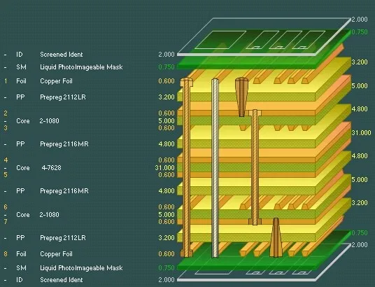
Engineers often use hybrid stackups combining low-loss cores for critical RF layers with cost-effective prepregs elsewhere. Surface smoothness (low-profile copper) further reduces skin-effect losses.
Fundamental Principles of Signal Integrity Optimization
Transmission line theory underpins mmWave PCB design, treating traces as distributed elements with characteristic impedance defined by geometry and materials. Maintaining 50-ohm impedance prevents reflections that distort waveforms. Low-loss dielectrics with dissipation factors below common FR-4 levels minimize attenuation per unit length. Symmetric stackups ensure uniform fields, reducing mode conversion in differential pairs.
Coupling to ground planes confines fields, suppressing radiation and crosstalk. Via optimization, such as backdrilling or blind vias, eliminates unused stub lengths that resonate at mmWave. Controlled impedance calculations account for frequency-dependent effects like surface roughness. These principles form the basis for high-frequency PCB layout in 5G equipment.
Best Practices for High-Frequency PCB Layout
Start with stackup planning to dedicate inner layers for signals between power and ground planes, providing return paths and shielding. Use microstrip or stripline configurations based on accessibility needs, with striplines preferred for lower radiation. Route critical signals first, keeping lengths matched and bends as 45-degree miters or curves to avoid discontinuities. Maintain minimum spacing of three times the trace width to curb crosstalk.
Segregate analog RF from digital baseband to prevent noise injection. Employ stitching vias along trace edges for stable reference planes. Simulate layouts early to predict eye diagrams and insertion loss. Fabricate prototypes with tight tolerances to validate models.
Performance specifications in IPC-6012 outline qualification criteria for rigid boards, guiding fabrication for high-reliability applications. Adhering to these ensures boards meet electrical demands.
Achieving Impedance Control in 5G PCBs
Impedance control in 5G PCBs requires precise trace width, thickness, and spacing calculations using field solvers. Frequency dispersion in dielectrics necessitates broadband models for accurate predictions. Manufacturing tolerances on copper etching and plating directly affect final impedance, demanding statistical process control. Test coupons on panels verify compliance post-etch. Engineers working on 5G base stations can benefit from our overview of 5G telecommunication base station PCB design challenges and solutions.
Hybrid stackups with low-loss cores and standard prepregs balance cost and performance. Edge plating or castellations aid transitions to connectors. Dynamic adjustments during design iterations refine control. This systematic impedance control 5G PCB approach sustains signal fidelity across bands.
Strategies to Minimize Signal Loss in mmWave Designs
Select materials with low loss tangents and stable permittivities to curb dielectric absorption. Smooth copper surfaces reduce skin effect losses by minimizing roughness scattering. Minimize via count through fanout optimization and embedded components. Use embedded transmission lines to shorten paths and enhance shielding.
Thermal management prevents loss variations from heating. Ground plane continuity avoids slots that increase inductance. Post-layout extraction confirms total insertion loss budgets. These tactics collectively address signal loss 5G PCB concerns.
Suggested Reading: High Frequency PCB Routing Techniques: Minimizing Signal Loss and Interference
Via Design, HDI, and Backdrilling for mmWave
Vias introduce inductance and capacitance discontinuities at mmWave frequencies. Strategies include backdrilling to remove unused stubs, which can otherwise resonate and cause notches in the frequency response. Blind and buried vias, along with high-density interconnect (HDI) microvias (as small as 0.1 mm), reduce stub length and improve routing density.
Via-in-pad plated over (VIPPO) and filled vias provide smoother transitions and better thermal/electrical performance. Impedance-matched via transitions and anti-pad optimization further reduce reflections. HDI enables compact multilayer designs common in 5G front-ends while maintaining signal integrity.
Antenna Integration and Phased Array PCB Considerations
Phased array antennas in 5G base stations require tight integration with RF front-ends on the same PCB or package. Antenna-in-Package (AiP) or Antenna-on-PCB approaches use low-loss materials and precise feed networks to maintain gain and beamforming accuracy.
Key considerations include minimizing feed line losses, ensuring uniform phase distribution across elements, and managing mutual coupling. HDI and multilayer techniques support dense array layouts. Simulation of the entire structure—including bending effects on flexible sections or warpage—is critical. Careful ground plane design and shielding prevent unwanted radiation or EMI.
Advanced Troubleshooting for mmWave Signal Issues
When eye diagrams show closure, inspect for impedance steps at vias or pads. TDR measurements pinpoint mismatches along lines. Crosstalk victims exhibit ringing; increase separation or add guards. Excessive loss traces to material or roughness; cross-section analysis reveals culprits.
Warpage alters clearances; flatness specs per IPC standards mitigate this. Phase imbalance in pairs signals stackup asymmetry. Iterative prototyping refines solutions. Logical diagnosis preserves 5G performance.
2026 Trends and Future-Proofing mmWave Designs
In 2026, trends include wider adoption of ultra-low-loss laminates (e.g., LCP for antennas), advanced HDI with microvias for higher density, and hybrid constructions combining rigid and flexible sections. Phased arrays continue scaling with integrated AiP solutions, while 5G-Advanced and early 6G explorations push frequencies higher.
Future-proof designs by incorporating bandwidth headroom, modular stackups for material swaps, and simulation-driven verification that accounts for manufacturing variation. Early collaboration with fabricators on tolerances and processes helps balance performance, yield, and cost as networks evolve.
Conclusion
Optimizing signal integrity in 5G network equipment PCBs demands a holistic approach encompassing materials, layout, and verification. MmWave frequencies amplify every design choice, from stackup symmetry to via management. Implementing high-frequency PCB layout best practices ensures impedance control and minimal signal loss. Engineers benefit from structured adherence to proven principles, yielding reliable mmWave performance. Future 5G evolutions will further emphasize these techniques for sustained innovation.
FAQs
Q1: What is 5G PCB signal integrity, and why is it critical for mmWave frequencies?
A1: 5G PCB signal integrity involves maintaining signal waveform quality against distortions like reflections and attenuation. At mmWave frequencies, short wavelengths make PCBs act as antennas, heightening sensitivity to parasitics. Poor integrity causes data errors in network equipment. Logical stackup and routing preserve eye opening and jitter margins. Adhering to design standards ensures robust transmission.
Q2: How does mmWave PCB design differ from lower-frequency layouts?
A2: MmWave PCB design prioritizes low-loss materials and precise transmission lines due to dominant skin and dielectric effects. High-frequency PCB layout demands shorter traces, fewer vias, and continuous grounds to curb radiation. Impedance mismatches cause severe reflections at these bands. Simulations predict behaviors absent in GHz designs. This shift supports 5G's high throughput.
Q3: What techniques improve impedance control in 5G PCBs?
A3: Impedance control 5G PCB relies on field solver-based width calculations, tolerant etching, and test coupons. Symmetric dielectrics stabilize values across frequencies. Backdrilling vias smooth transitions. Manufacturing feedback loops refine processes. These ensure 50-ohm lines for reflection-free paths.
Q4: How can engineers reduce signal loss 5G PCB in network gear?
A4: Reduce signal loss 5G PCB by selecting low-Df laminates, smoothing copper, and optimizing vias. Shielded striplines confine fields, minimizing radiation. Thermal controls prevent dynamic shifts. Verification via VNA confirms low insertion loss. Structured practices yield efficient mmWave channels.
References
IPC-2221B — Generic Standard on Printed Board Design. IPC, 2012
IPC-6012E — Qualification and Performance Specification for Rigid Printed Boards. IPC, 2017
IPC-A-600K — Acceptability of Printed Boards. IPC, 2020


