Introduction
The rollout of 5G networks has transformed PCB design requirements, pushing engineers to handle frequencies from sub-6 GHz up to millimeter-wave bands beyond 20 GHz. Traditional PCB design tools often fall short in predicting behaviors at these speeds, leading to issues like signal degradation and thermal hotspots. Selecting appropriate 5G PCB design software becomes essential for ensuring reliable performance in base stations, antennas, and user equipment. High-frequency PCB simulators integrated within these tools enable precise modeling of electromagnetic fields, transmission lines, and power distribution networks. This article explores key considerations for choosing PCB design tools that support advanced simulations, focusing on signal integrity and thermal management. Engineers must prioritize software capabilities aligned with industry demands for low loss and high data rates.
Why High-Frequency Simulation Matters in 5G PCB Design
5G applications operate at much higher frequencies than previous generations, introducing phenomena such as skin effect, dielectric dispersion, and radiation losses that degrade signal quality. Without accurate simulation, prototypes may exhibit unexpected insertion loss or crosstalk, delaying time-to-market and increasing costs. A robust high-frequency PCB simulator allows engineers to virtualize these effects early, optimizing stackups and routing before fabrication. Compliance with standards like IPC-2221C for generic printed board design ensures designs meet performance thresholds for controlled impedance and layer alignment. Moreover, thermal analysis software PCB integration reveals heat dissipation challenges from high-power RF components. Ultimately, these tools bridge the gap between theoretical models and real-world manufacturing variability.
In 5G networks, signal paths must maintain integrity over complex multilayer structures, where via transitions and bends introduce discontinuities. Simulations predict S-parameters accurately, guiding impedance matching to 50 ohms or differential pairs. Power integrity analysis complements this by modeling PDN resonances that couple noise into signals. Engineers benefit from software that couples electromagnetic and circuit simulations for holistic validation. This approach minimizes iterations, aligning with qualification specs in IPC-6012F for rigid printed boards.
Key Technical Challenges in High-Frequency 5G PCBs
At millimeter-wave frequencies, conductor surface roughness significantly amplifies losses, as fields concentrate near metal surfaces due to skin effect. Dielectric materials must exhibit low dissipation factors to minimize absorption, yet their anisotropy complicates field uniformity across layers. Software must model these accurately using full-wave solvers to compute effective permittivity variations. Vias act as stubs that reflect energy unless back-drilled or optimized, requiring precise 3D geometry extraction from layout. Crosstalk between adjacent traces escalates with proximity and frequency, demanding coupled-line analysis for far-end and near-end predictions.
Thermal effects exacerbate these issues, as RF power amplifiers generate localized heat that alters material properties and expands traces, shifting impedances. Coupled electro-thermal simulations track junction temperatures and CTE mismatches. Radiation from antennas integrated on PCBs requires pattern optimization to avoid interference with nearby circuits. Engineers need tools that handle hybrid solver methods, blending method-of-moments for planar structures with finite-element for 3D components. Adherence to IPC-6018D for high-frequency microwave boards guides qualification tests like thermal shock and signal attenuation measurements.
Power delivery networks in 5G PCBs face simultaneous switching noise at gigabit rates, creating voltage droops that jitter timing margins. Decoupling capacitor placement demands frequency-dependent impedance profiling. Advanced PCB design tools incorporate IBIS-AMI models for channel simulations up to PAM4 modulation. Material libraries with frequency-dispersive data enable realistic loss tangents from 1 GHz to 100 GHz. These features allow iterative optimization of plane shapes and stitch vias for low-inductance paths.
Essential Features of 5G PCB Design Software
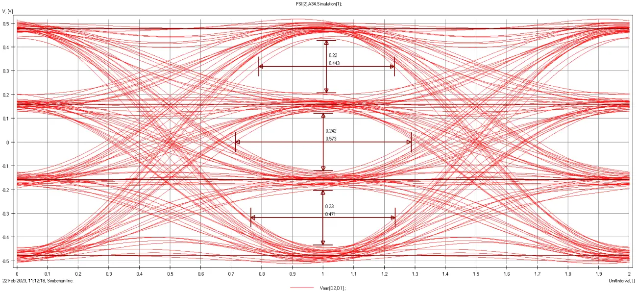
Effective 5G PCB design software integrates layout editing with a high-frequency PCB simulator for seamless pre- and post-layout analysis. Look for 3D electromagnetic solvers supporting arbitrary geometries, including embedded passives and transitions to packages. Frequency-domain extraction of S-parameters, Y-parameters, and touchstone files facilitates system-level integration. Time-domain capabilities handle transient responses for eye diagram generation and compliance checks against bit error rates. Solver acceleration via GPU or cloud computing handles large designs with thousands of ports.
Signal integrity simulators within these tools should support multi-gigabit serdes models, including equalization pre/de-emphasis and clock recovery. Automated impedance calculators based on physical equations verify stripline and microstrip targets. For power integrity, plane impedance solvers compute spreading impedance spectra, identifying resonance peaks. Coupled SI/PI workflows simulate crosstalk under simultaneous switching. Engineers appreciate scripting interfaces for parametric sweeps over stackup thicknesses or widths.
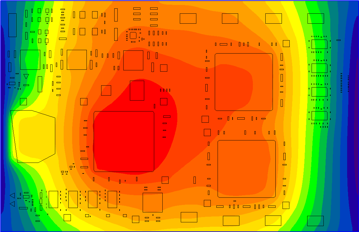
Thermal analysis software PCB modules solve heat equations coupled with electrical losses, predicting hotspots from trace currents and die heating. Multi-physics engines import Joule heating from EM results, iterating on via thermal resistance and spreader designs. Material thermal conductivity libraries account for copper fill factors and via densities. Visualization tools overlay temperature contours on 3D models, aiding heatsink placement decisions. Validation against thermal cycling aligns with performance specs.
User interface efficiency matters for complex 5G boards with dense routing. Drag-and-drop solver setup from layout reduces setup time. Post-processing includes field visualizations for intuition on modes and losses. Export to manufacturing formats preserves sim-verified geometries. Scalability to HDI structures with blind vias supports sub-6 mil lines.
Best Practices for Selecting and Using These Tools
Start by evaluating solver accuracy through benchmarks on known structures like coupled lines or discontinuities, comparing against measurements. Prioritize software with validated material models for low-loss laminates, ensuring Df predictions match vendor data. Integration with design rule checks automates compliance during routing. For team workflows, version control and collaborative simulation runs enhance productivity.
Implement a simulation-driven workflow: model stackup first, simulate PDN, then route critical nets with real-time verification. Parametric studies optimize trade-offs between loss, cost, and density. Always correlate sims with prototypes using VNA for S-params and TDR for impedances. Document assumptions like surface roughness factors for reproducibility.
Hybrid simulations combining quasi-static for low-freq and full-wave for high-freq balance speed and precision. Couple with SPICE for active components like LNAs. Regular updates ensure support for emerging 5G evolutions like sub-THz. Training on advanced features maximizes ROI.
Conclusion
Choosing the right 5G PCB design software hinges on robust high-frequency PCB simulator capabilities, signal integrity simulators, and thermal analysis software PCB integration. These tools address core challenges of loss minimization, integrity preservation, and heat management in millimeter-wave designs. Alignment with standards like IPC-6018D ensures manufacturable, reliable boards. Engineers gain confidence through accurate predictions, reducing prototype spins. Invest in scalable, user-friendly platforms to future-proof 5G and beyond deployments. Prioritize features matching specific application frequencies and densities for optimal results.
FAQs
Q1: What key features should electric engineers prioritize in 5G PCB design software?
A1: Engineers should seek integrated high-frequency PCB simulators with 3D full-wave solvers for accurate S-parameter extraction at mmWave bands. Signal integrity simulators handling IBIS-AMI models and eye diagrams ensure data integrity. Thermal analysis software PCB coupling reveals heat impacts on performance. Parametric optimization and material libraries streamline stackup decisions, aligning with IPC-2221C guidelines for efficient workflows.
Q2: Why is signal integrity simulation critical for high-frequency 5G PCBs?
A2: At 5G frequencies, skin effect and dielectric losses distort waveforms, causing inter-symbol interference. Signal integrity simulators predict crosstalk, reflections, and equalization needs pre-layout. They model via stubs and bends accurately, optimizing impedance control. This prevents BER failures in prototypes, supporting dense routing per IPC-6012F specs. Overall, it accelerates design convergence.
Q3: How does thermal analysis integrate with PCB design tools for 5G applications?
A3: Thermal analysis software PCB imports electrical losses to simulate hotspots from RF power. It couples CTE effects on traces, predicting warpage risks. Multi-layer conduction paths including vias are modeled for realistic gradients. Engineers optimize copper pours and thermal vias iteratively. This ensures reliability under continuous operation.
Q4: What role do industry standards play in validating high-frequency PCB simulators?
A4: Standards like IPC-6018D define performance metrics for microwave boards, such as attenuation and phase stability. Simulators benchmark against these for solver fidelity. IPC-2221C guides impedance and layer designs. Validation builds trust in predictions, bridging sim to fab outcomes without fabrication trials.
References
IPC-6018D — Qualification and Performance Specification for High Frequency (Microwave) Printed Boards. IPC, 2022
IPC-2221C — Generic Standard on Printed Board Design. IPC, 2023
IPC-6012F — Qualification and Performance Specification for Rigid Printed Boards. IPC, 2023