Introduction
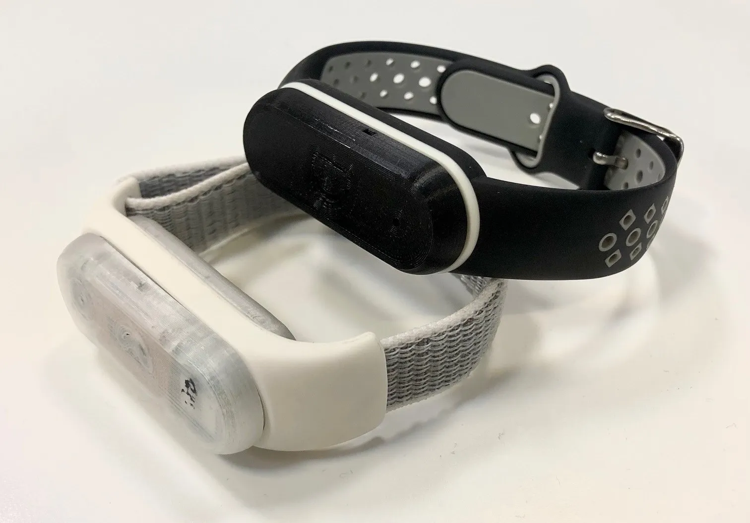
Wearable fitness trackers have revolutionized personal health monitoring by integrating sensors, processors, and batteries into compact, body-conforming devices. These gadgets track steps, heart rate, sleep patterns, and more, all while enduring constant motion and flexing. At the heart of their functionality lies the flexible PCB, which allows electronics to bend and twist without failure. Flexible PCB design for wearable fitness trackers prioritizes durability, miniaturization, and reliability under dynamic stresses. Engineers must balance electrical performance with mechanical resilience to ensure long-term operation. This guide explores the principles, design strategies, material choices, and assembly hurdles specific to these applications.
What Are Flexible PCBs and Why They Matter in Wearable Fitness Trackers
Flexible printed circuit boards, or flex PCBs, consist of conductive traces embedded in a flexible dielectric substrate, typically enabling single-sided, double-sided, or multilayer configurations. Unlike rigid boards, they accommodate bending, folding, and dynamic movement, making them ideal for space-constrained environments. In wearable fitness trackers, flex PCBs connect sensors like accelerometers and optical heart rate monitors to microcontrollers and power sources within slim profiles. This adaptability reduces overall device thickness and weight, enhancing user comfort during extended wear. Moreover, flex PCBs minimize wiring harnesses, lowering assembly complexity and potential failure points from vibrations. Their relevance stems from the need to conform to irregular body contours, such as wrists or chests, while maintaining signal integrity.
The shift toward flex PCBs in fitness trackers addresses limitations of rigid boards, which crack under repeated flexing. Standards like IPC-2223 provide guidelines for sectional design in flexible printed boards, ensuring consistent performance. Engineers appreciate how these boards support high-density interconnects without sacrificing bend cycles. Ultimately, flex PCBs enable sleeker designs that boost battery life through optimized routing paths. As trackers evolve with more features, like GPS and ECG monitoring, the demand for robust flex solutions intensifies.
Flex vs Rigid PCBs: When to Choose Flex for Trackers
Rigid PCBs (typically FR-4) excel in applications requiring high mechanical stability, multilayer complexity, and cost efficiency for stationary or low-vibration environments. However, they lack the ability to conform to curved surfaces or endure dynamic motion.
Flex PCBs (or rigid-flex hybrids) are the preferred choice for fitness trackers because they:
- Conform to irregular body contours (wrists, chest) for better fit and comfort.
- Withstand millions of bend cycles from daily movement.
- Enable thinner, lighter designs by replacing connectors and cables.
- Reduce overall assembly complexity and potential failure points.
Rigid-flex constructions combine the best of both worlds: rigid sections for mounting processors, batteries, or displays, and flexible sections for bending areas. Choose pure flex or rigid-flex when the design requires 3D shaping, vibration resistance, or space savings that rigid boards cannot deliver. For simple, low-power trackers with minimal motion, rigid PCBs may suffice, but most modern devices benefit from flex technology for durability and user experience.
Key Principles of Flexible PCB Design for Wearable Fitness Trackers
Flexible PCB design for wearable fitness trackers begins with defining bend zones, where the board will repeatedly flex, and stiffener areas for component mounting. Engineers segment the layout into static and dynamic regions, routing traces perpendicular to bend lines to distribute strain evenly. Minimum bend radii depend on layer count and copper thickness, with wider traces in flex areas to prevent cracking. Adhesives and coverlays protect traces, while vias placement avoids high-stress points. Simulation tools model strain distribution, predicting fatigue over millions of cycles. This structured approach aligns with engineering logic for reliability.
Material selection influences design profoundly, with polyimide dominating due to its balance of flexibility and thermal properties. Copper foil type, rolled annealed versus electrodeposited, affects ductility in dynamic zones. Stackup planning integrates rigid sections for connectors or batteries, forming rigid-flex hybrids common in trackers. Signal integrity demands controlled impedance traces, especially for high-speed sensor data. Thermal management routes heat away from skin-contact areas. Ground planes shield against EMI from body movement.
Designers incorporate tear stops and strain-relief features at edges to mitigate propagation failures. Component footprints favor low-profile parts, positioned on rigid islands. Testing protocols verify bend endurance, mimicking wrist motions. Compliance with IPC-2223 ensures designs withstand operational stresses. These principles enable trackers to endure sweat, impacts, and flexing without delamination.
Suggested Reading: How to Design a Reliable Bluetooth Antenna on a Fitness Tracker PCB
Polyimide PCB Benefits for Fitness Trackers
Polyimide serves as the premier substrate for flex PCBs in fitness trackers, offering exceptional mechanical flexibility alongside high-temperature tolerance. This material withstands repeated bending without embrittlement, crucial for devices strapped to moving limbs. Polyimide PCB benefits for fitness trackers include superior chemical resistance to sweat and lotions, preventing degradation over time. Its low moisture absorption maintains dielectric stability, vital for accurate sensor readings. Engineers value polyimide's dimensional stability under thermal cycling, reducing trace misalignment.
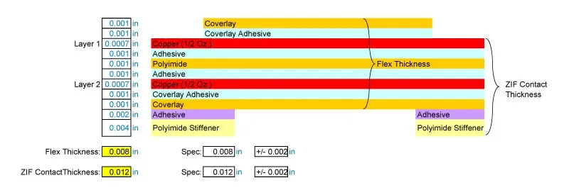
The thin profile of polyimide films, often 25 to 50 microns, supports ultra-compact tracker designs. It bonds effectively with copper, enabling fine-pitch traces for dense sensor arrays. Radiation resistance and low outgassing suit prolonged skin contact. Compared to polyester alternatives, polyimide handles higher assembly temperatures without warping. This reliability translates to fewer field returns for battery or sensor failures.
Polyimide's fatigue resistance supports over 100,000 bend cycles in dynamic zones, aligning with tracker lifecycles. It facilitates lightweight construction, under half the weight of rigid FR-4 equivalents. Electrical properties like low dissipation factor preserve battery efficiency. Troubleshooting common issues, such as coverlay adhesion, involves optimizing lamination pressures. Overall, polyimide empowers innovative form factors without compromising performance.
Compared to alternatives like polyester (PET) or PEN, polyimide handles higher assembly temperatures without warping and provides superior long-term reliability in skin-contact applications.
| Property | Polyimide (PI) | PET/PEN | LCP (for RF) |
|---|---|---|---|
| Flexibility | Excellent (dynamic) | Good (lower cycles) | Good |
| Thermal Stability | High (-200°C to +300°C) | Moderate | High |
| Moisture Absorption | Low | Higher | Very low |
| Cost | Medium-High | Low | High |
| Best for Trackers | Dynamic flex, durability | Cost-sensitive static | High-frequency sensors |
Polyimide’s low dissipation factor helps preserve battery life, while its radiation and chemical resistance minimize field failures.
Flex PCB Assembly Challenges and Solutions
Flex PCB assembly challenges arise from the material's delicacy, demanding specialized handling to avoid creases or tears. Thin substrates complicate fixturing during SMT placement, as vacuum nozzles risk pulling material. Engineers troubleshoot by using custom carriers that support the entire panel. Solder paste application requires precise stencils to prevent bridging on fine pitches. Reflow profiles must account for polyimide's lower Tg, avoiding excessive heat exposure.
Component alignment on flex areas poses risks of tombstoning due to uneven contraction. Solutions include anchoring with stiffeners and sequential soldering. IPC-6013 outlines qualification specs for flexible boards, guiding inspection criteria like adhesion strength. Peel tests verify coverlay integrity post-assembly. Rework demands low-heat tools to prevent substrate damage.
Dynamic stresses during conformal coating application can cause bubbling; vacuum-assisted processes mitigate this. Testing assembled boards involves flex cycling under electrical load, simulating usage. Common pitfalls like via cracking stem from over-flexing in test handlers. Practical fixes include zoned routing and encapsulation. These strategies ensure trackers pass drop and bend qualifications.
Best Practices for Reliable Flex PCBs in Fitness Trackers
Start with thorough DFM reviews, focusing on bend radius compliance and material specs. Collaborate early with fabricators to optimize panelization for yield. Employ finite element analysis for strain hotspots. Select adhesives matching polyimide CTE for lamination. Prototype iteratively, incorporating field data from beta wearers. For wearable-specific challenges like sweat exposure and constant motion, review our guide on flexible PCBs for smart eyewear as a complementary case study.
Quality control spans visual, electrical, and mechanical tests per IPC-A-610 acceptability criteria. Microsectioning reveals internal voids. Environmental screening simulates sweat exposure via salt fog chambers. Documentation traces revisions for traceability. These practices minimize defects in production ramps.
Sustainability considerations favor recyclable polyimides where feasible. Engineer for disassembly to extend component life. Monitor assembly metrics like first-pass yield. Continuous improvement refines processes for next-gen trackers.
Future Trends in Flexible PCBs for Wearables
Looking ahead to 2026 and beyond, trends include ultra-thin and stretchable circuits for better skin conformity, integration of transparent or perovskite-based flexible electronics, and higher-density interconnects supporting AI-driven health insights. Rigid-flex and hybrid constructions will proliferate, alongside advanced materials like LCP for RF-heavy designs and sustainable polyimide variants.
Expect increased adoption of stretchable printed circuits in medical-grade wearables, smarter textiles, and devices with embedded sensors for continuous biomarker monitoring. These advancements will enable even slimmer, more comfortable trackers with extended battery life and enhanced reliability under constant motion.
Conclusion
Flexible PCBs form the backbone of modern wearable fitness trackers, enabling ergonomic, durable designs that withstand real-world rigors. From polyimide's robust properties to strategic layouts per IPC standards, engineers can achieve high reliability. Addressing flex PCB assembly challenges through fixturing and testing ensures production success. Prioritizing these elements delivers devices that track health accurately over years. As demands grow for multifunctional trackers, mastering flex technology remains key.
FAQs
Q1: What are the main considerations in flexible PCB design for wearable fitness trackers?
A1: Flexible PCB design for wearable fitness trackers emphasizes bend zones, minimum radii, and strain distribution to prevent trace fatigue. Use polyimide for dynamic areas and stiffeners for components. Route signals perpendicular to flex lines and simulate stresses early. Adhere to IPC-2223 for guidelines. This approach balances compactness with longevity under motion.
Q2: How do polyimide PCB benefits enhance fitness tracker performance?
A2: Polyimide PCB benefits for fitness trackers include high flexibility, thermal stability, and chemical resistance to sweat. It supports thin profiles for comfort and repeated bends without cracking. Low moisture uptake ensures signal reliability for sensors. These traits reduce weight and enable conformal shapes, improving user experience and battery life.
Q3: What are common flex PCB assembly challenges and how to overcome them?
A3: Flex PCB assembly challenges involve handling thin materials, fixturing for SMT, and reflow without damage. Use custom carriers, precise stencils, and tailored profiles. IPC-6013 aids qualification. Test for adhesion and cycle endurance. Troubleshooting focuses on sequential processes to maintain integrity.
Q4: Why choose flex PCBs over rigid ones for fitness trackers?
A4: Flex PCBs conform to body shapes, reducing bulk and wiring failures in trackers. They endure vibrations better than rigid boards, which crack under flex. Polyimide enables lightweight, durable builds. Assembly simplifies interconnections. Overall, they support advanced features in slim packages.
References
IPC-2223 — Sectional Design Standard for Flexible Printed Boards. IPC
IPC-6013 — Qualification and Performance Specification for Flexible Printed Boards. IPC
IPC-A-610 — Acceptability of Electronic Assemblies. IPC


