Introduction
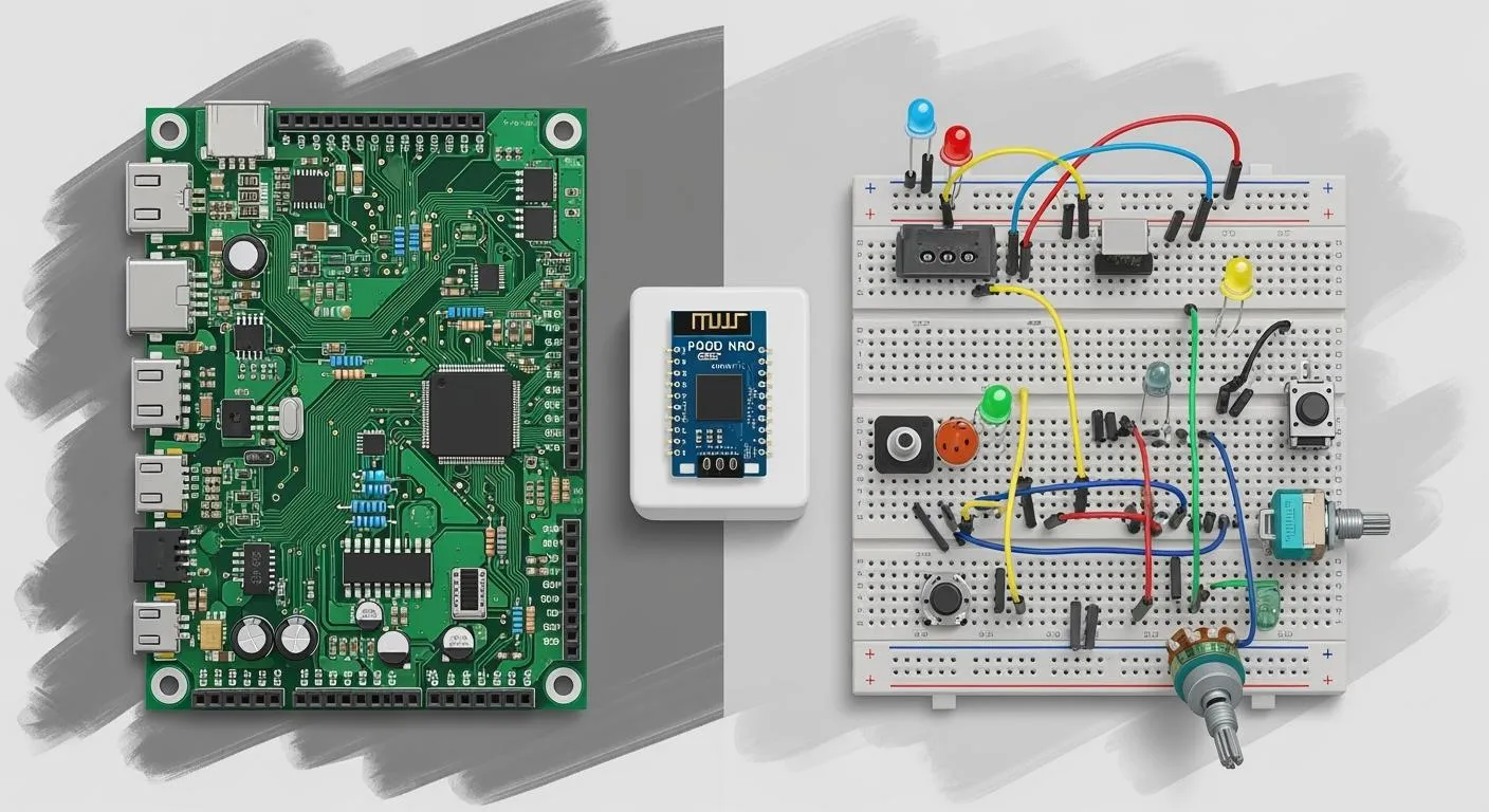
Breadboards serve as an excellent starting point for electronic hobbyists to prototype circuits quickly and without permanent commitments. However, they come with limitations such as loose connections that can fail under vibration or prolonged use, unreliable contacts over time, and challenges in scaling to more complex designs. Moving beyond the breadboard to printed circuit boards (PCBs) allows hobbyists to create more reliable and compact circuits. FR-1 PCBs, in particular, offer an accessible and cost-effective option for this transition. These boards enable FR-1 PCB circuit construction that balances affordability with sufficient performance for many hobbyist projects. By mastering building circuits on PCB with FR-1 material, enthusiasts can achieve durable circuit design suitable for everyday applications like sensors, timers, and simple amplifiers.
What Is FR-1 PCB and Why It Matters for Hobbyists
FR-1 PCB refers to a type of single-sided laminate made from paper reinforced with phenolic resin, achieving flame retardancy classified under UL94 V-0 standards. This material contrasts with more advanced laminates like FR-4, which use glass fabric for higher mechanical strength and thermal resistance. For electronic hobbyists, FR-1 stands out due to its low cost and ease of processing, making it ideal for prototyping and low-volume production. It supports through-hole component mounting, which aligns well with the hand-assembly techniques common among hobbyists. The relevance of FR-1 lies in its ability to facilitate FR-1 PCB circuit construction without requiring expensive equipment or high-precision fabrication. Hobbyists benefit from its availability in pre-perforated boards or custom-etched formats, bridging the gap between temporary prototypes and permanent builds.
In practical terms, FR-1 excels in low-frequency, low-power applications where environmental stresses are minimal, such as battery-powered gadgets or educational kits. Its surface finish accepts solder easily, promoting strong joints essential for durable circuit design. While not suited for high-speed signals or multilayer needs, FR-1 empowers hobbyists to focus on circuit functionality rather than material overkill. Understanding FR-1 properties helps in selecting it over pricier alternatives for non-critical projects. This choice supports building circuits on PCB that are mechanically stable and electrically reliable for extended use. For a complete manufacturing overview, read our guide on Mastering the FR-1 PCB Manufacturing Process: A Step-by-Step Guide.
Key Advantages of FR-1 for Robust Circuit Building
FR-1 PCBs provide several advantages that make them a smart upgrade from breadboards for hobbyists seeking durability. The phenolic base offers good dimensional stability under normal operating conditions, reducing the risk of trace breaks from flexing. Its natural matte finish improves solder wetting compared to glossy alternatives, leading to fewer cold joints during assembly. Cost savings allow hobbyists to iterate designs multiple times without budget constraints, fostering experimentation in durable circuit design. Additionally, FR-1's lower density makes boards lighter, beneficial for portable projects like wearables or remote sensors. Compare FR-1 with other materials in our detailed FR1 vs FR2 vs FR3 vs FR4: How to Choose the Right PCB Material.
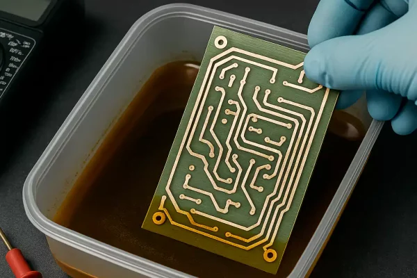
Another benefit is the material's compatibility with standard etching processes using common chemicals, enabling hobbyists to fabricate custom boards at home. This hands-on approach teaches valuable skills in FR-1 PCB circuit construction while producing boards ready for immediate population. The single-sided nature simplifies routing, minimizing crosstalk in simple analog circuits. Hobbyists appreciate how FR-1 handles moderate heat from soldering irons without immediate delamination, provided best practices are followed. Overall, these traits position FR-1 as a foundational material for transitioning to professional-grade building circuits on PCB.
Designing Durable Circuits on FR-1 PCBs
Effective design begins with planning trace widths and spacing to accommodate current loads and prevent overheating in FR-1 PCB components. Hobbyists should aim for generous clearances around pads to ease soldering and reduce bridging risks. Software tools or graph paper sketches help visualize layouts before committing to etching, ensuring signal integrity in analog sections. Incorporating mounting holes early supports enclosure integration, enhancing mechanical robustness. For durable circuit design, prioritize through-hole components over surface-mount for better heat dissipation during hand assembly.
Component selection plays a crucial role; choose FR-1 PCB components like resistors, capacitors, and transistors rated for the board's thermal limits. Avoid high-power devices that could char the phenolic substrate. Layout symmetry minimizes stress concentrations that lead to warpage over time. Test points strategically placed allow in-circuit debugging without desoldering. Adhering to these principles results in circuits that withstand daily handling far better than breadboard equivalents.
Best Practices for Soldering on FR-1 PCBs
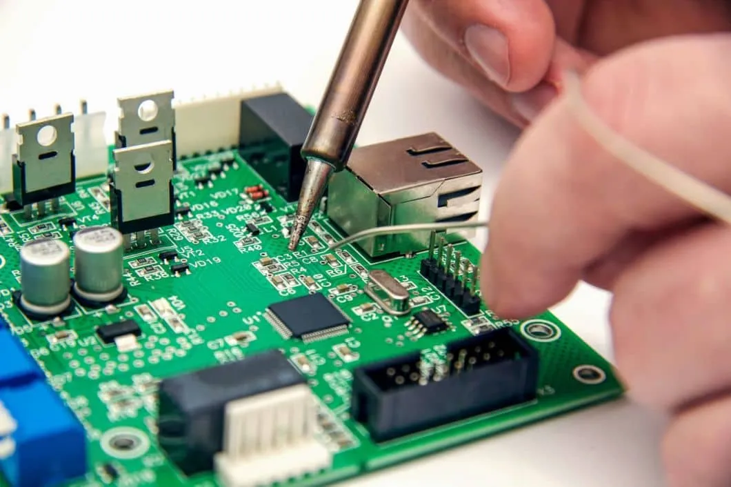
Soldering on FR-1 PCB demands attention to temperature control to preserve the material's integrity. Use a soldering iron set to around 300-350 degrees Celsius for brief contacts, allowing flux to activate without scorching the phenolic. Apply flux sparingly to pads and leads, then tin components before insertion for smoother joints. Heat the joint from the component side first to draw solder evenly, avoiding prolonged iron dwell that could lift traces. Clean residues promptly with isopropyl alcohol to prevent corrosion in humid environments. Ensure your FR-1 builds stay reliable—check our analysis of The Shocking Truth About FR-1 PCB Temperature Limits.
Following guidelines from J-STD-001 ensures professional-quality solder joints suitable for hobbyist reliability. Inspect each connection for shine and fillet formation, rejecting dull or cracked appearances. For multi-pin devices, tack corners first to align properly before filling in. Practice on scrap FR-1 pieces builds confidence in handling the material's quirks, like slight charring at edges if overheated. These steps make soldering on FR-1 PCB a straightforward process that yields durable circuit design ready for enclosure.
Selecting and Mounting FR-1 PCB Components
FR-1 PCB components should prioritize through-hole types for secure mechanical retention and heat management. Resistors and capacitors in axial packages fit naturally, providing stability against vibration. Diodes and transistors with sturdy leads anchor well, distributing stress evenly across pads. LEDs and potentiometers add functionality without overwhelming the single-layer constraints. Selecting components with pre-tinned leads simplifies soldering on FR-1 PCB and improves joint strength.
Mounting sequence matters: start with lowest-profile parts to maintain board flatness. Bend leads to fit pad spacing precisely, avoiding sharp angles that weaken solder bonds. Secure taller components like electrolytic capacitors with adhesive if needed for transport. This methodical approach supports building circuits on PCB that endure drops and thermal cycling. Testing continuity post-assembly verifies all FR-1 PCB components integrate correctly before powering up.
Troubleshooting Common Issues in FR-1 Builds
Warpage often arises from uneven etching or asymmetric component loading, addressable by symmetric layouts and controlled drying post-fabrication. Solder bridges between traces require wick and flux for removal, preventing shorts in dense areas. Trace lifts from excessive heat signal overtinned pads or dirty surfaces; mitigate with fresh flux and minimal iron time. Component tombstoning in uneven heating favors sequential soldering from board center outward. Per IPC-A-600 criteria, visual checks confirm acceptability, catching defects early.
Delamination at edges from moisture exposure calls for baking boards pre-assembly and conformal coating post-soldering. Signal noise in audio circuits traces to ground plane absence; improvise with wide ground traces. Power supply ripple demands adequate decoupling capacitors near ICs. Systematic troubleshooting refines skills in FR-1 PCB circuit construction, turning setbacks into robust designs.
Conclusion
Transitioning to FR-1 PCBs elevates hobbyist projects from fragile prototypes to reliable devices through thoughtful FR-1 PCB circuit construction. Key elements like proper design, component choice, and soldering techniques ensure durable circuit design withstands real-world use. Standards such as J-STD-001 and IPC-A-600 guide quality without complexity. Hobbyists gain satisfaction from compact, vibration-resistant builds that outperform breadboards. Experimenting with FR-1 fosters deeper electronics understanding, paving the way for advanced materials. Embrace building circuits on PCB to unlock endless creative potential.
FAQs
Q1: What is involved in FR-1 PCB circuit construction for beginners?
A1: FR-1 PCB circuit construction starts with designing a layout on paper or software, etching the board with chemicals like ferric chloride, and cleaning thoroughly. Drill holes for through-hole components, then solder them following temperature guidelines to avoid material damage. Test continuity before power-up. This process suits hobbyists for simple projects, yielding durable results with practice. Keywords like building circuits on PCB emphasize the hands-on reliability.
Q2: How do I ensure safe soldering on FR-1 PCB?
A2: Soldering on FR-1 PCB requires a controlled iron temperature, flux application, and quick joints to prevent charring the phenolic base. Tin components first and heat from the lead side for even flow. Clean flux residues immediately to avoid corrosion. Per J-STD-001, shiny fillets indicate success. This approach builds confidence in durable circuit design for hobbyist applications.
Q3: What FR-1 PCB components work best for durable designs?
A3: FR-1 PCB components like axial resistors, ceramic capacitors, and TO-92 transistors provide mechanical strength and thermal compatibility. Avoid high-power parts that stress the substrate. Pre-bend leads for secure fit and add decoupling for stability. Proper selection supports robust FR-1 PCB circuit construction in low-stress environments.
Q4: Why choose FR-1 for building circuits on PCB as a hobbyist?
A4: FR-1 enables affordable building circuits on PCB with easy etching and soldering, ideal for single-sided prototypes. It offers better durability than breadboards against vibration and handling. Limitations suit non-critical apps, focusing learning on layout and assembly skills. This material accelerates progress toward professional durable circuit design.
References
J-STD-001G — Requirements for Soldered Electrical and Electronic Assemblies. IPC, 2011
IPC-A-600K — Acceptability of Printed Boards. IPC, 2020
IPC-6012E — Qualification and Performance Specification for Rigid Printed Boards. IPC, 2017


