Differential Signaling
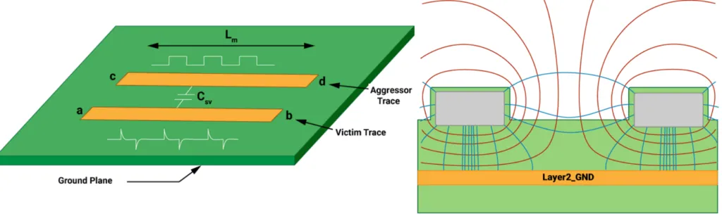
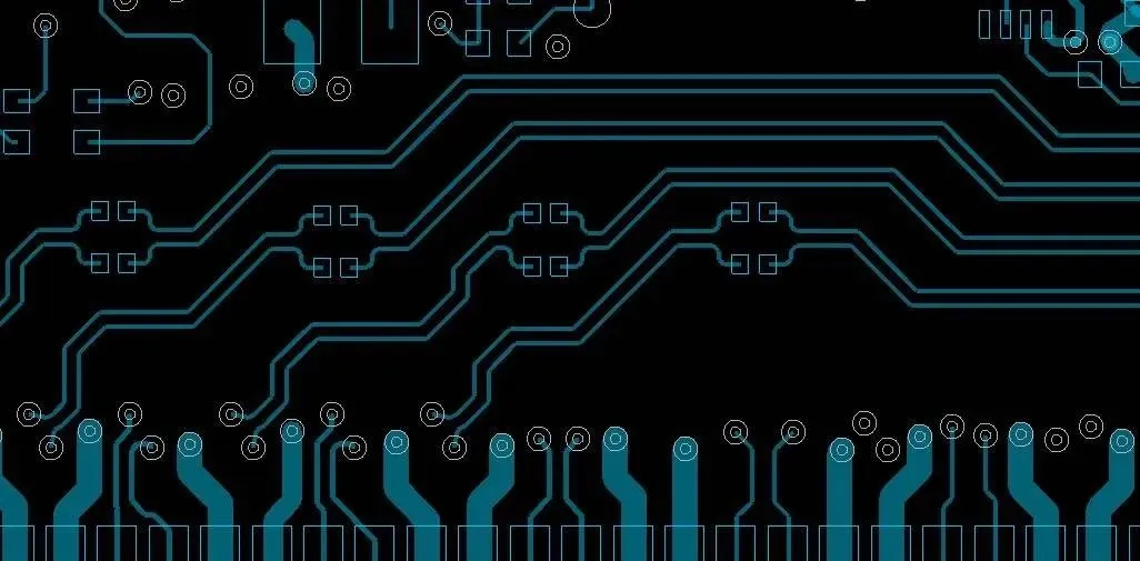
Differential signaling is a fundamental technique in electronics and PCB design that transmits data using a pair of complementary signals, where the information is encoded in the difference between the two lines rather than their absolute values. This approach is particularly valuable for engineers and designers seeking to enhance signal integrity in high-speed circuits, as it effectively minimizes electromagnetic interference (EMI), common-mode noise, and crosstalk that can degrade performance in single-ended systems. For those searching for insights on differential signaling, this tag encompasses a range of topics from basic principles to advanced implementations. Understanding differential signaling allows you to achieve reliable data transmission over longer distances and at higher frequencies, making it essential for applications such as USB, HDMI, Ethernet, and automotive networks. In PCB layouts, proper use of differential pairs ensures controlled impedance, which is critical for maintaining signal quality and preventing reflections that could lead to data errors. Practical applications include routing differential traces with equal lengths to avoid skew, incorporating termination resistors to match impedances, and selecting appropriate connectors for low-loss performance. Best practices also involve simulating signal paths using tools like SPICE or field solvers to predict and mitigate issues before fabrication. By applying these methods, you can optimize designs for robustness in noisy environments, such as industrial controls or telecommunications equipment. The resources under this tag offer detailed explorations of these concepts, including case studies on troubleshooting common pitfalls and integrating differential signaling with mixed-signal boards. Reviewing these articles can provide the guidance needed to refine your projects and stay ahead in evolving electronics standards.
Video Guide
No videos found for this tag.
Technical Articles
Get in Touch
Send Message
- Products & Service
- Company
- About AIVON
- Contact
- News
- Blog
- Certification
-


- Payment
-


2026 AIVON.COM All Rights Reserved