Introduction
Crystal oscillators provide the precise timing signals essential for microcontrollers, communication devices, and many hobbyist projects. When they fail to oscillate, entire circuits can stop working, leading to frustration during prototyping or repairs. Crystal oscillator troubleshooting becomes a key skill for electronic hobbyists dealing with PCB-based designs. Common issues often stem from assembly errors, layout problems, or component mismatches rather than the crystal itself. This guide offers practical steps to diagnose and fix crystal oscillator circuit problems, helping you get back to building. By following a systematic approach, you can identify issues like crystal oscillator not oscillating without advanced equipment.
Crystal Oscillator Basics: Why Troubleshooting Matters
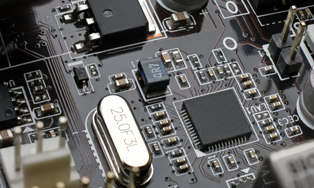
A crystal oscillator uses a quartz crystal's piezoelectric properties to generate a stable frequency, typically in the Pierce or Colpitts configuration on PCBs. These circuits include load capacitors, resistors, and connections to a microcontroller's XTAL pins. For hobbyists, they power Arduino clones, clocks, and sensors where accuracy matters. Troubleshooting matters because failures disrupt timing, causing erratic behavior or no operation at all. Early detection saves time and components during crystal oscillator repair. Understanding basics prevents repeated mistakes in future builds.
Reliable oscillation depends on matching the crystal's load capacitance and ensuring sufficient loop gain. Poor performance leads to symptoms like no output signal or slow startup. Hobbyists often encounter this in custom boards where PCB traces introduce stray effects. Addressing these ensures stable operation across temperatures and voltages.
Crystal Resonator Flaw Inspection: Common Oscillator Circuit Problems
Crystal oscillator not oscillating frequently results from mismatched load capacitors, where the series combination of C1 and C2 plus strays exceeds the crystal's specified capacitance. This reduces loop gain, preventing startup. Long PCB traces add unwanted capacitance or inductance, detuning the circuit. Soldering flux residue increases leakage, shunting the high-impedance feedback path. Power supply noise from poor decoupling couples into the oscillator, causing instability.
Overdriving the crystal occurs when loop gain is too high, often from low series damping resistors or high supply voltage, leading to damage over time. Contaminants like fingerprints or humidity lower insulation resistance around the crystal. Mechanical stress during handling fractures the hermetic seal, allowing moisture ingress. Incorrect pin connections or loose joints from hasty soldering compound these issues. Environmental factors, such as operating outside recommended temperatures, exacerbate marginal designs.
Layout flaws on PCBs, like routing noisy signals nearby, inject crosstalk that kills oscillation. Insufficient ground plane separation creates loops picking up EMI. In surface-mount assemblies, overheating during soldering warps the crystal case or degrades internals. These problems highlight why crystal oscillator troubleshooting starts with inspection.
Step-by-Step Crystal Oscillator Troubleshooting Guide
Begin with a visual inspection of the PCB. Check for cracked solder joints, flux residue, or bent crystal leads using a magnifying glass or microscope. Verify component values match the datasheet: load capacitors typically 10-30 pF, feedback resistors around 1 MOhm. Ensure no shorts across pins with a multimeter set to continuity. Clean the area with isopropyl alcohol if residue is present, as it often resolves leakage issues.
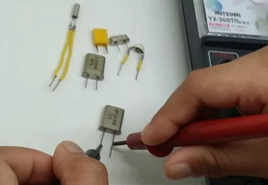
Next, power up the circuit and use a multimeter for basic crystal oscillator testing multimeter checks. Measure DC supply voltage at the oscillator pins; it should match the datasheet, usually 3.3V or 5V. Check resistance across the crystal: infinite or very high (megohms) indicates no internal short. Probe for voltage drops across resistors to confirm current flow. Avoid loading the circuit heavily, as hobbyist multimeters can dampen weak signals. If voltages are correct but no oscillation suspected, proceed to signal checks.
Acquire an oscilloscope if available, the best tool for confirming oscillation. Probe the output pin (often EXTAL) with a 10x probe to minimize loading. Look for a clean sine or clipped sine wave at the expected frequency, say 16 MHz for common MCUs. Check startup time: stable signal within milliseconds after power-on. If flatline, probe input pin for feedback signal. A "finger test" helps: lightly touch the input pin; if oscillation starts or frequency shifts slightly, loop gain is marginal but present. For more on startup failures, see our guide to debugging crystal oscillator startup issues.
Test under stress conditions for thorough diagnosis. Vary supply voltage slightly and observe waveform stability. Heat the board gently with a hairdryer or cool with freezer spray to simulate temperature extremes, as gain drops at high temps. Introduce noise by turning on nearby motors or LEDs. If failure occurs, suspect layout or decoupling. For crystal oscillator repair, reflow suspicious joints with a hot air station, following proper profiles to avoid damage.
Advanced hobbyists can perform a loop gain margin test. Temporarily insert a potentiometer (1-10 kOhm) in series with one crystal leg. Slowly increase resistance until oscillation stops; it should tolerate at least twice the crystal's ESR. This confirms sufficient drive without overdriving. Replace capacitors if strays are high, measuring with an LCR meter off-board.
Best Practices for Crystal Oscillator Circuits
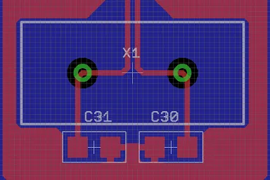
Keep PCB traces under 10 mm for oscillator components, placing them close to MCU pins. Use a solid ground plane but cut it under sensitive traces to reduce capacitance. Route power and ground symmetrically with multiple vias. Decouple the supply with 0.1 uF and 10 uF caps nearby. Adhering to IPC J-STD-001 requirements for soldering ensures clean joints without excess flux, critical for high-impedance circuits.
Select crystals with low ESR for faster startup and margin against variations. Account for 2-5 pF stray capacitance in load calculations. In Pierce configurations, add a series resistor (22-100 Ohm) to limit drive level. Avoid Colpitts if possible due to DC bias risks; block it with a large capacitor if used. Test prototypes across voltage and temperature ranges early. Learn advanced stability techniques in our guide to maximizing crystal oscillator stability.
For assembly, preheat PCBs gently and use no-clean flux sparingly. Inspect joints per IPC-A-610 criteria for acceptability, checking for voids or bridges. These practices minimize crystal oscillator circuit problems in hobby projects.
Real-World Crystal Oscillator Troubleshooting Insights
In one hobbyist scenario, a 16 MHz crystal failed to oscillate on a custom AVR board due to 22 pF caps instead of 18 pF, plus 4 pF strays overloading it. Swapping to 15 pF fixed it instantly. Another case involved flux residue post hand-soldering; cleaning restored operation. Marginal gain showed as long startup, resolved by larger feedback resistor.
Layout crosstalk from adjacent USB traces halted a sensor project. Rerouting and shielding worked. Overdriven low-frequency crystals (4 MHz) hummed then died; adding damping helped. These examples underscore systematic crystal oscillator troubleshooting over guesswork.
Conclusion
Mastering crystal oscillator troubleshooting empowers hobbyists to build reliable timing circuits. Start with inspection and multimeter basics, escalate to scope analysis, and apply layout best practices. Common fixes like capacitor tweaks or cleaning resolve most crystal oscillator not oscillating issues. Reference standards like J-STD-001 during assembly for professional results. With these steps, your PCB projects will oscillate steadily, reducing repair time and boosting success.
FAQs
Q1: How do I test a crystal oscillator with a multimeter?
A1: Crystal oscillator testing multimeter starts with DC voltage checks at pins and infinite resistance across the crystal. Probe supply rails for stability around 3.3V or 5V. Check no shorts or excessive current draw. While not detecting oscillation directly, it rules out power or connection faults quickly. Follow up with a scope for waveform confirmation in troubleshooting.
Q2: Why is my crystal oscillator not oscillating?
A2: Crystal oscillator not oscillating often comes from load capacitance mismatch, flux residue, or long PCB traces adding strays. Power noise or poor grounding also kills loop gain. Inspect soldering and clean if needed. Verify datasheet values for caps and resistors. Short traces and decoupling caps usually fix it for hobbyists.
Q3: What are common crystal oscillator circuit problems on PCBs?
A3: Crystal oscillator circuit problems include soldering defects, layout-induced parasitics, and overdriving from high gain. Flux leakage shunts feedback, while EMI from nearby signals disrupts startup. Temperature extremes reveal marginal designs. Follow clean assembly and short routing to prevent them.
Q4: How to repair a faulty crystal oscillator circuit?
A4: Crystal oscillator repair involves reflowing joints, replacing mismatched capacitors, and cleaning residue. Check layout for long traces and add decoupling. Test with scope post-fix. If damaged, swap the crystal ensuring spec match. Proper soldering per standards avoids recurrence.
References
J-STD-001G — Requirements for Soldered Electrical and Electronic Assemblies. IPC, 2017
IPC-A-610H — Acceptability of Electronic Assemblies. IPC, 2019
IEC 60122-1 — Quartz crystal units for frequency control and selection — Part 1: Basic specification. IEC, 2002


