Introduction
Edge computing has transformed how AI workloads are processed, bringing computation closer to data sources for reduced latency and enhanced efficiency. AI accelerator PCBs, which host specialized processors for tasks like neural network inference, play a central role in these systems. In harsh environments such as industrial automation, autonomous vehicles, and remote sensing, these boards face extreme challenges including temperature fluctuations, mechanical vibrations, and moisture exposure. Designing AI accelerator PCB edge computing solutions requires a focus on ruggedized PCB design AI principles to ensure reliability and performance. Engineers must balance high-speed signal integrity with environmental robustness, making material selection and protection strategies critical. This article explores key design considerations to help electric engineers create durable boards that withstand demanding conditions.
What Are AI Accelerator PCBs in Edge Computing and Why Do Harsh Environments Matter?
AI accelerator PCBs integrate high-performance chips optimized for parallel processing in edge devices, enabling real-time AI decisions without cloud dependency. These boards feature dense layouts with multiple layers, fine-pitch components, and power delivery networks to support intensive computations. Edge computing applications deploy these PCBs in field settings where low latency is essential, such as predictive maintenance in factories or obstacle detection in drones. Harsh environments introduce stressors like prolonged vibration, thermal cycling, and corrosive humidity that can degrade solder joints, delaminate layers, or cause electrical shorts. Without proper ruggedized PCB design AI, failures lead to system downtime and safety risks in critical operations. Understanding these dynamics guides engineers toward proactive mitigation.
Key Challenges in Harsh Environments for AI Accelerator PCBs
High power dissipation from AI accelerators generates localized heat, exacerbating thermal stress in fluctuating ambient conditions. Vibration and shock from machinery or vehicle motion induce fatigue in interconnects, particularly fine-pitch BGAs common in these designs. Moisture ingress promotes corrosion and dendritic growth, compromising insulation resistance over time. Electromagnetic interference compounds issues in dense layouts, while dust accumulation hinders cooling. These factors demand integrated solutions across material, layout, and protection domains. Electric engineers must prioritize challenges based on application profiles to optimize AI accelerator PCB edge computing performance.
Thermal Management for Extended Temperature Range AI PCB
Maintaining functionality across wide temperature swings requires materials with matched coefficients of thermal expansion to components. Multilayer stackups with dedicated power and ground planes distribute heat evenly, reducing hotspots under AI workloads. Thermal vias arrayed beneath high-power chips conduct heat to outer layers or attached sinks effectively. Component selection favors industrial-grade parts tolerant of extremes, while layout avoids clustering heat sources. Simulation verifies dissipation paths before fabrication. This approach ensures extended temperature range AI PCB reliability without performance throttling. For sensor-specific applications facing similar stresses, see our guide on Designing High Reliability Industrial Sensor PCBs for Harsh Environments.
Vibration and Shock Resistance in AI Accelerator PCBs
Dynamic loads cause micro-cracks in solder joints and trace tears, especially in flexible regions of the board. Strategic placement anchors heavy components near mounting points, minimizing leverage effects. Thicker copper weights and wider traces enhance mechanical strength against cyclic stress. Stiffeners or ribs added to flex areas prevent excessive deflection during operation. Enclosure integration with damping materials further isolates the PCB. Vibration resistance AI PCB design thus preserves signal integrity in mobile edge applications.
Materials Selection for Ruggedized PCB Design AI
Laminate choices emphasize high glass transition temperatures and low moisture absorption for thermal and humidity resilience. Polyimide substrates offer superior stability in demanding scenarios compared to standard epoxies. Copper foil types with low profile roughness support high-frequency signals while resisting fatigue. Core and prepreg matching ensures stackup uniformity, preventing warpage from asymmetric expansion. Adhesives with robust bonding maintain interlayer integrity under stress. These selections form the foundation of ruggedized PCB design AI tailored for edge AI demands.
Here is a comparison of common materials for rugged AI accelerator PCBs:
| Material | Tg (°C) | CTE (ppm/°C, z-axis) | Moisture Absorption | Key Advantages | Best Applications |
|---|---|---|---|---|---|
| High-Tg FR-4 | 170–190 | 25–40 | Moderate | Cost-effective, good processability | General industrial edge devices |
| Polyimide (PI) | 250–260 | 15–25 | Very low | Excellent thermal/mechanical stability | Extreme temperature & vibration |
| BT/Epoxy Blend | 180–220 | 20–35 | Low | Balanced electrical & thermal performance | High-speed AI signal paths |
| Hydrocarbon/Ceramic-filled | 200+ | Low | Very low | Superior high-frequency & thermal properties | High-power density accelerators |
Polyimide and specialized low-loss resins outperform standard epoxies in demanding scenarios. Low-profile copper foils support high-frequency signals while resisting fatigue. Matched core/prepreg combinations and robust adhesives prevent warpage and maintain interlayer integrity under combined thermal and mechanical stress.
Suggested Reading: AI Accelerator PCBs for Automotive Applications: Meeting Stringent Safety and Reliability Standards
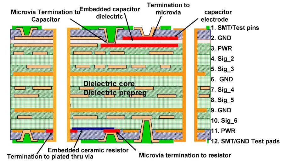
PCB Layout and Stackup Strategies
Controlled impedance traces preserve AI accelerator signal quality amid environmental noise. HDI structures with microvias enable dense routing for compact edge devices, but require blind and buried via planning to avoid stubs. Power integrity demands decoupled planes with minimal loops to supply bursty AI loads stably. Symmetric stackups counter warpage from thermal mismatch. Edge beveling and mounting hole reinforcement aid mechanical fixation. Following IPC-2221 guidelines for spacing and sizing ensures manufacturability and reliability in harsh settings.
Suggested Reading: Build Your Own AI Accelerator: A Hobbyist's Custom PCB Guide
Protection Techniques: Conformal Coating and Encapsulation for AI PCBs
Conformal coatings form a thin barrier against moisture, chemicals, and fungal growth, applied uniformly via spray or dip methods. Silicone variants provide flexibility for vibration-prone uses, while urethanes excel in abrasion resistance. Qualification per IPC-CC-830 verifies dielectric strength, adhesion, and flexibility post-cure. Selective masking protects connectors and fiducials during application. Potting offers heavier encapsulation for ultimate shielding in corrosive atmospheres. Conformal coating AI PCB strategies extend service life significantly in edge deployments.
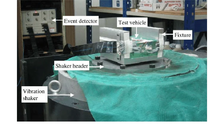
Mechanical Reinforcement and Testing Protocols
Support features like edge clamps and conformal stiffeners distribute loads evenly across the board. Underfill beneath large packages secures attachments against shear forces. Qualification testing simulates combined stressors, including random vibration profiles and thermal shock cycles. IPC-6012 specifications define acceptance criteria for high-reliability boards, covering visual, electrical, and mechanical inspections. Post-test analysis via cross-sectioning reveals hidden defects. These protocols validate vibration resistance AI PCB and overall robustness.
Multi-Physics Simulation and Verification Workflows
Multi-physics simulation integrates electromagnetic, thermal, and mechanical domains to predict real-world behavior. Tools model Joule heating from AI workloads, CTE-induced warpage, and vibration-induced stress simultaneously.
Workflows typically start with stackup and PDN analysis, followed by full 3D EM simulation of critical nets, thermal mapping, and structural FEA for vibration modes. Iterative optimization refines via placement, copper distribution, and reinforcement features. Correlation with accelerated life testing validates models, reducing prototype spins and ensuring ruggedized PCB design meets field requirements.
Real-World Case Studies and Deployment Lessons
In industrial predictive maintenance systems, one deployment switched to polyimide-based boards with dense thermal vias and silicone conformal coating, reducing field failures by over 60% in high-vibration factory environments while maintaining inference performance.
An autonomous drone application used HDI with underfill and selective potting to survive extreme temperature swings and shocks, extending operational MTBF significantly. Lessons include the value of early multi-physics simulation to catch warpage issues and the importance of application-specific environmental profiling—over-protecting increases cost and weight, while under-protecting leads to costly recalls.
Best Practices for Implementation
Begin with environmental profiling to prioritize stressors, informing material and layout decisions early. Collaborate across design, fabrication, and assembly for DFM adherence. Prototype iterations incorporate test feedback, refining protections iteratively. Documentation traces decisions to standards, aiding qualification. Scalable designs accommodate future AI chip evolutions without full redesigns. These practices streamline ruggedized PCB design AI for production.
2026 Trends in Rugged Edge AI Accelerator PCBs
In 2026, trends include wider adoption of advanced heterogeneous integration (chiplets and 2.5D/3D packaging) for higher performance in smaller footprints, ultra-low-loss materials with improved thermal conductivity, and AI-assisted design tools for multi-physics optimization.
Increased focus on sustainable rugged materials (halogen-free, recyclable) and modular designs supports easier field upgrades. Enhanced conformal coatings with self-healing properties and integrated sensors for in-situ health monitoring are gaining traction. These advancements enable more powerful, reliable edge AI accelerators in increasingly demanding environments.
Conclusion
AI accelerator PCB edge computing thrives in harsh environments through meticulous attention to thermal, mechanical, and protective elements. Ruggedized approaches, from high-stability materials to conformal coating AI PCB layers, mitigate risks effectively. Vibration resistance AI PCB and extended temperature range AI PCB features ensure operational continuity. Engineers leveraging standards like IPC-2221, IPC-CC-830, and IPC-6012 achieve compliant, reliable outcomes. Prioritizing these considerations positions edge systems for long-term success in demanding fields.
FAQs
Q1: What are the primary design challenges for AI accelerator PCB edge computing in harsh environments?
A1: Engineers face thermal hotspots from high-power AI chips, solder joint fatigue from vibration, and corrosion from humidity. Ruggedized PCB design AI addresses these via matched CTE materials, reinforced joints, and protective barriers. Layout optimization minimizes stress concentrations, while testing verifies endurance. This holistic method sustains performance where standard boards fail.
Q2: How does conformal coating AI PCB enhance reliability in moist conditions?
A2: Conformal coating AI PCB applies a dielectric layer shielding circuits from ingress and contaminants. It prevents shorts and insulation degradation per IPC-CC-830 qualification. Flexible types absorb vibration without cracking, extending lifespan. Application uniformity ensures complete coverage, with masking for accessibility. Troubleshooting focuses on adhesion tests post-exposure.
Q3: What strategies improve vibration resistance AI PCB for edge devices?
A3: Vibration resistance AI PCB employs stiffeners, secure mounting, and robust traces to counter dynamic loads. Component placement near supports reduces leverage, while underfill bolsters BGAs. Testing simulates operational profiles to identify weaknesses early. Stackup symmetry aids overall rigidity. These tactics maintain interconnect integrity in mobile applications.
Q4: Why is extended temperature range AI PCB critical for industrial edge computing?
A4: Extended temperature range AI PCB uses high-Tg laminates and thermal vias to handle cycles without delamination. Power planes spread heat, preventing throttling during AI inference. Material CTE matching avoids cracks in assemblies. IPC-6012 compliance guides qualification for reliability. This ensures uninterrupted operation in factories or outdoors.
References
IPC-6012E — Qualification and Performance Specification for Rigid Printed Boards. IPC, 2017
IPC-2221B — Generic Standard on Printed Board Design. IPC, 2012
IPC-CC-830B — Qualification and Performance of Electrical Insulating Compounds for Printed Wiring Board Coating. IPC, 2014


