Introduction
Reflow soldering remains a cornerstone of surface mount technology assembly, where solder paste melts to form reliable joints between components and printed circuit boards. Proper component orientation directly influences the uniformity of heat exposure during this process, helping to prevent defects that compromise assembly yield and reliability. Engineers often encounter issues like tombstoning and the shadow effect, which arise from suboptimal placement strategies. Understanding these interactions allows for reflow soldering optimization, ensuring consistent results across production runs. This article delves into component placement guidelines and practical strategies tailored for electrical engineers tackling real-world assembly challenges.
Understanding Reflow Soldering and the Role of Component Orientation
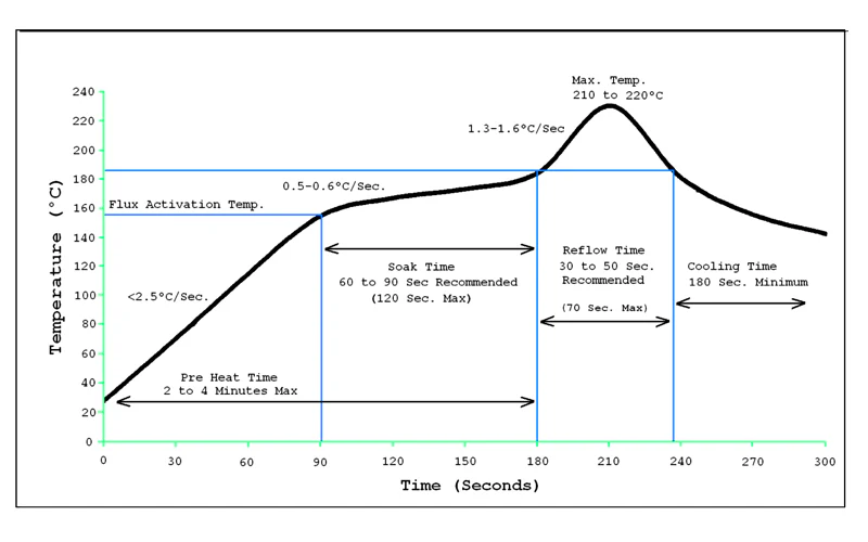
Reflow soldering involves heating the assembled PCB through a controlled oven profile, typically featuring preheat, soak, reflow, and cooling zones to activate flux, melt solder, and solidify joints. Component orientation refers to the alignment and positioning of parts relative to each other and the board's travel direction in the reflow oven. Poor orientation can lead to uneven heating, where factors like thermal mass differences exacerbate defects. For instance, components with higher thermal mass absorb heat more slowly, potentially delaying solder melting on one side compared to lighter parts. Adhering to component placement guidelines during design and pick-and-place setup minimizes these risks. In high-volume manufacturing, optimizing orientation enhances throughput while reducing rework. For a complete walkthrough of the temperature zones and profile development, see our companion reflow soldering process guide.
Key Defects Linked to Component Orientation
Tombstoning occurs when one end of a chip component lifts vertically during reflow, often due to asymmetric solder paste melting driven by orientation and thermal gradients. This defect stands out in small passives like 0201 or 0402 resistors, where surface tension pulls the part upright if one pad wets before the other. The shadow effect, prevalent in infrared-dominated reflow systems, happens when taller components block radiant heat from reaching smaller ones behind them, resulting in incomplete soldering. Thermal mass variations amplify both issues, as denser parts cool slower and create localized cold spots. Engineers must prioritize component orientation to balance heat distribution across the board. Proactive design reviews catch these pitfalls early.
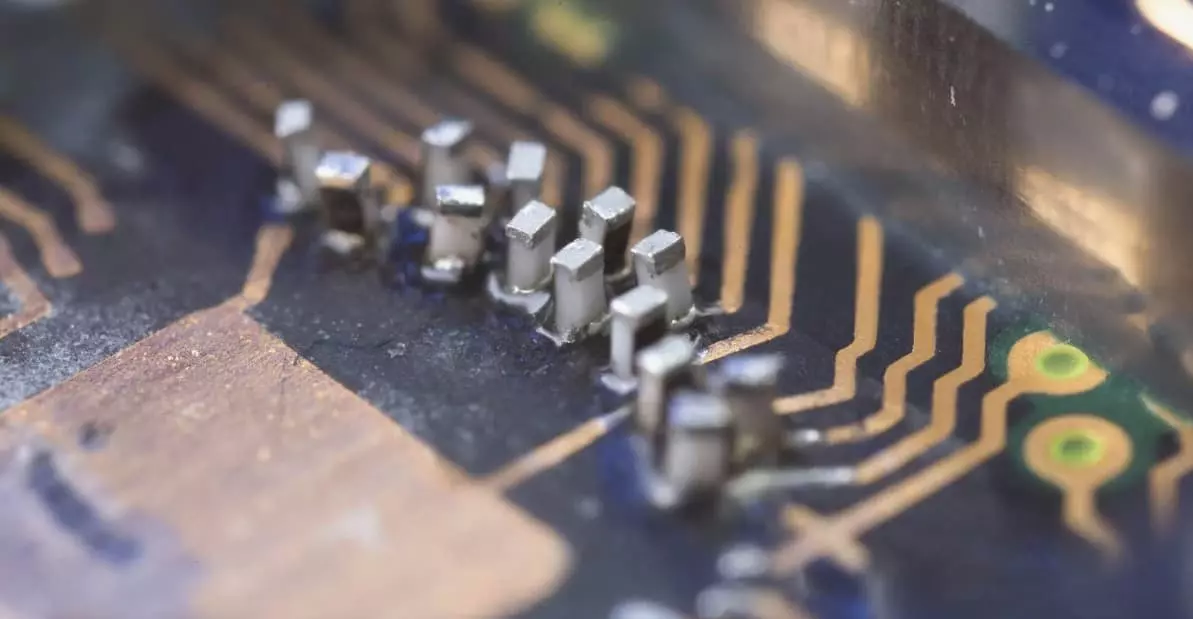
Table: Common Defects Linked to Component Orientation
| Defect | Primary Orientation Cause | Typical Impact | IPC Reference |
|---|---|---|---|
| Tombstoning | Asymmetric heating due to rotation or thermal mass mismatch | Lifted termination, open circuit | IPC-A-610, J-STD-001 |
| Shadow Effect | Tall component upstream of small passive in airflow path | Cold joints, insufficient solder | IPC-7530B |
| Voids | Rapid outgassing in shadowed or high-mass areas | Reduced reliability, especially in QFN | IPC-7095 |
| Cold Joints | Insufficient heat reach due to orientation and conveyor direction | Weak mechanical bond | IPC-A-610 |
Technical Principles: Thermal Mass, Heat Transfer, and Shadow Effect
Heat transfer in reflow ovens relies on convection, conduction, and radiation, with component orientation dictating exposure efficiency. Components aligned parallel to the conveyor direction experience more uniform airflow, reducing gradient-induced stresses. Thermal mass, defined by a part's size, density, and material, determines its heating rate; heavier parts like inductors lag behind lighter resistors, promoting uneven reflow. The shadow effect intensifies when small components trail larger ones in the oven's airflow path, starving them of convective heat. J-STD-020 provides classification for component reflow sensitivity, guiding placement to avoid such mismatches. Balancing these principles through simulation and profiling ensures robust joints. Engineers should validate these principles with real-time data using thermal profiling best practices for reflow ovens.
In convection reflow, dominant in modern lines, orientation perpendicular to airflow can create turbulence pockets, further complicating heat uniformity. Engineers simulate thermal profiles to predict shadow zones, adjusting layouts accordingly. Pad design symmetry, per IPC J-STD-001 soldering requirements, complements orientation by equalizing wetting forces.
Impact of Reflow Oven Types on Optimal Orientation
Reflow oven technology significantly influences the effectiveness of component orientation strategies.
Forced convection ovens, the industry standard in 2026, provide relatively uniform heating but remain sensitive to shadowing. Best practices include orienting chip components parallel to the conveyor and placing tall parts upstream of low-profile passives. Nitrogen atmospheres can improve wetting but may exacerbate tombstoning with certain solder pastes by increasing surface tension; test profiles carefully when using nitrogen.
Infrared (IR) ovens, still used in some legacy or specialized lines, amplify the shadow effect because radiant heat travels in straight lines. Here, generous spacing (≥2× the height difference) and staggered orientation become critical. Vapor phase soldering offers the most uniform heat transfer via condensation, dramatically reducing both shadow effect and thermal mass sensitivity. Orientation remains important mainly for paste volume symmetry and to prevent component floating or shifting.
Hybrid systems combining convection and IR require the most careful layout validation. Always match orientation rules to the specific oven type used in production.
Component Placement Guidelines for Defect Prevention
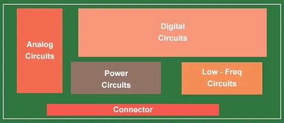
Effective component placement guidelines start with grouping parts by thermal mass, placing high-mass components away from board edges where cooling ramps steeper. Orient chip resistors and capacitors parallel to the conveyor to symmetrize heating across terminations. Maintain minimum spacing between tall and short components to mitigate shadow effects, typically at least twice the height difference. For mixed-technology boards, position bottom-terminated devices to avoid airflow obstruction. Validate layouts against oven-specific profiles during prototyping. These practices form the backbone of tombstoning prevention and reflow soldering optimization.
Designers should also consider board warpage, as bowed surfaces alter standoff distances and orientation effectiveness. Symmetrical pad geometries ensure balanced solder volume transfer.
Quantitative Guidelines and IPC Standards
Modern reflow profiles follow strict quantitative limits. Preheat ramp rates should stay below 3 °C/s (ideally 1–2 °C/s) to minimize tombstoning, solder beading, and graping, especially with 0201 and smaller components. Soak time is typically 60–120 seconds between 150–180 °C for SAC alloys. Peak temperature usually ranges 235–245 °C with time above liquidus (TAL) of 45–90 seconds. Cooling rates of 3–6 °C/s prevent excessive intermetallic growth.
Bow and twist limits (commonly ≤0.75 % for Class 3 boards) are critical because warpage alters effective orientation and standoff. Paste volume ratios should be balanced within ±10 % between paired pads. IPC-7530B (2025 revision) provides updated guidelines for temperature profiling across reflow, wave, selective, and vapor phase processes, emphasizing thermocouple attachment methods, profile acceptance criteria, and data analysis for orientation-related gradients.
J-STD-020E and IPC J-STD-001 remain foundational for MSL classification and soldering acceptability. Regular profilometer runs, combined with these standards, ensure empirical validation of orientation decisions.
Best Practices for Reflow Soldering Optimization
Optimize preheat and soak zones to equalize temperatures before reflow peak, compensating for thermal mass disparities regardless of orientation. Use nitrogen atmospheres to reduce oxidation, enhancing wetting uniformity and minimizing shadow-induced voids. Fine-tune conveyor speed and zone lengths to match board size, preventing orientation-related gradients. Solder paste selection with balanced activity supports consistent reflow across varied components. IPC-7530 outlines temperature profiling techniques to verify these settings empirically. Regular profilometer runs confirm adherence, troubleshooting deviations promptly. Cross-reference defect patterns with our detailed overview of common SMT PCB assembly defects for broader root-cause analysis.
Component placement accuracy within 50 microns prevents paste offset, a common tombstoning trigger. Post-placement inspection flags misorientations before reflow.
Troubleshooting Common Orientation-Related Defects
When tombstoning appears, first inspect pad sizes; undersized pads reduce paste retention, favoring one-sided pull. Adjust placement force to avoid component shift during transit to the oven. Shadow effect symptoms include cold joints on downstream small parts; reposition taller components upstream or increase spacing. Thermal profiling reveals mass-induced delays, prompting soak extension. Correlate defect maps with orientation patterns to iterate guidelines. Graceful troubleshooting restores yields without full redesigns.
For persistent issues, audit stencil apertures for volume consistency, as excess paste exacerbates capillary action imbalances.
Table: Troubleshooting Matrix for Orientation-Related Defects
| Defect | Likely Root Cause (Orientation Related) | Diagnostic Step | Corrective Action (IPC Reference) |
|---|---|---|---|
| Tombstoning | One-sided heating due to rotation or spacing | Check conveyor direction vs long axis | Re-orient parallel to conveyor; balance paste volume (J-STD-001 §8) |
| Shadow Effect / Cold Joint | Tall component blocking airflow to small part | Thermal profile downstream component | Reposition tall part upstream; increase spacing ≥2× height (IPC-7530B) |
| Voids in QFN | Trapped gas from rapid heating in shadowed area | X-ray + profile review | Adjust orientation and ramp rate <2 °C/s (IPC-7095) |
| Component Shift | Uneven wetting forces from thermal mass mismatch | AOI + profilometer data | Add fiducials, balance trace widths, re-orient (IPC-A-610) |
Advanced Strategies: Mixed Thermal Mass Assemblies
Boards with diverse components demand zoned heating or multi-stage reflow, but orientation tweaks often suffice. Place low-mass parts in preheat-favored positions, orienting them to maximize exposure. Simulate airflow with CFD tools to predict shadow zones pre-layout. Hybrid ovens blending convection and IR require extra vigilance on alignment. These tactics elevate reflow soldering optimization beyond basics.
Conclusion
Mastering component orientation unlocks defect-free reflow soldering, directly addressing tombstoning, shadow effects, and thermal mass challenges. Implementing placement guidelines and profiling best practices yields reliable assemblies for demanding applications. Electrical engineers benefit from proactive design and process controls, aligning with industry benchmarks. Prioritize these elements to streamline production and boost quality.
FAQs
Q1: How does component orientation prevent tombstoning in reflow soldering?
A1: Component orientation ensures symmetric heating across terminations, balancing solder wetting times. Align chips parallel to conveyor flow to minimize airflow gradients. Combine with precise paste deposition for optimal standoff. This approach, rooted in placement guidelines, reduces lift risks significantly during the reflow peak.
Q2: What is the shadow effect and how to mitigate it through placement?
A2: The shadow effect blocks heat from smaller components behind taller ones, causing incomplete reflow. Space parts adequately and position low-profile devices upstream of high-mass ones. Optimize orientation perpendicular to potential shadows. Reflow soldering optimization via profiling confirms uniform temperatures.
Q3: Why consider thermal mass in component placement guidelines?
A3: Thermal mass dictates heating rates, leading to uneven reflow if mismatched orientations cluster heavy parts. Group similar masses and distribute evenly. This prevents cold joints and supports tombstoning prevention. Profile validation ensures compliance across assemblies.
Q4: What role do standards play in reflow soldering optimization?
A4: Standards like J-STD-020 classify reflow sensitivity, guiding orientation for moisture-prone parts. IPC J-STD-001 specifies soldering criteria, including placement tolerances. They provide benchmarks for troubleshooting defects effectively.
References
IPC J-STD-001 — Requirements for Soldered Electrical and Electronic Assemblies. IPC, 2020
JEDEC J-STD-020E — Moisture/Reflow Sensitivity Classification of Nonhermetic Surface Mount Devices. JEDEC, 2014
IPC-7530 — Guidelines for Temperature Profiling of Printed Circuit Board Assemblies. IPC, 2008


