Industrial robots rely on tightly integrated electronic systems to achieve precise motion, real-time control, environmental perception, and reliable operation in demanding manufacturing environments. At the heart of every robot — from articulated arms to collaborative and mobile platforms — are advanced printed circuit boards (PCBs) that manage power distribution, signal processing, motor control, and communication between subsystems.
At Aivon, we specialize in high-reliability PCBs engineered specifically for robotics applications, supporting everything from compact collaborative robots to heavy-duty industrial arms like those from KUKA.
Fundamental Principles of Robot Operation and PCB Foundations
Robots convert digital commands into physical action through a closed-loop architecture: sensing, processing, decision-making, and actuation. This requires low-latency data flow, precise timing, and robust power delivery under continuous vibration, temperature variation, and electromagnetic interference.
PCB-level implications are significant:
- Real-time control cycles (often 1–8 ms) demand high-speed processors or motion controllers with optimized high-speed interfaces.
- Closed-loop feedback from encoders and sensors necessitates clean signal paths with minimal jitter and noise.
- Coordinated multi-axis movement relies on synchronized communication buses across multiple PCBs.
Modern robot controllers integrate these functions on multilayer boards using high-Tg FR4 or specialized laminates to maintain dimensional stability and electrical performance.
Key Components of Industrial Robots and Their PCB Requirements
Industrial robots typically consist of several interconnected subsystems, each placing unique demands on PCB design:
1. Controller and Main Processing Unit The robot controller serves as the brain, running motion planning, kinematics calculations, and safety logic. PCB considerations: High-performance multicore processors or DSPs require complex stack-ups with multiple power planes, controlled impedance routing for DDR memory and PCIe interfaces, and robust PDN design to support sustained high-frequency operation.
2. Servo Drives and Motor Control Servo motors (AC/DC) with integrated or external drives handle precise torque and position control. PCB design challenges: High-current traces for motor phases, thermal vias under power devices, and isolated gate driver circuits. Heavy copper layers (2–4 oz) and optimized layouts help manage heat dissipation while maintaining signal integrity for encoder feedback.
3. Sensor and Perception Systems Encoders, force-torque sensors, vision cameras, and proximity sensors provide essential feedback. PCB engineering: Low-noise analog front-ends, separate analog/digital grounding, and high-speed interfaces (LVDS, MIPI, Ethernet) for camera and LiDAR data. Careful component placement and shielding reduce crosstalk in electrically noisy environments.
4. Power Supply and Distribution Robots require multiple voltage rails for logic, I/O, and high-power actuators. PCB solutions: Multi-layer power planes, extensive decoupling, and point-of-load regulators. In compact designs, integrated power management PCBs help minimize voltage drops and improve efficiency.
5. Communication and I/O Interfaces Fieldbus protocols (EtherCAT, PROFINET, Modbus), digital/analog I/O, and safety networks connect the robot to external systems. PCB requirements: Differential pair routing with tight length matching and impedance control ensures reliable high-speed deterministic communication.
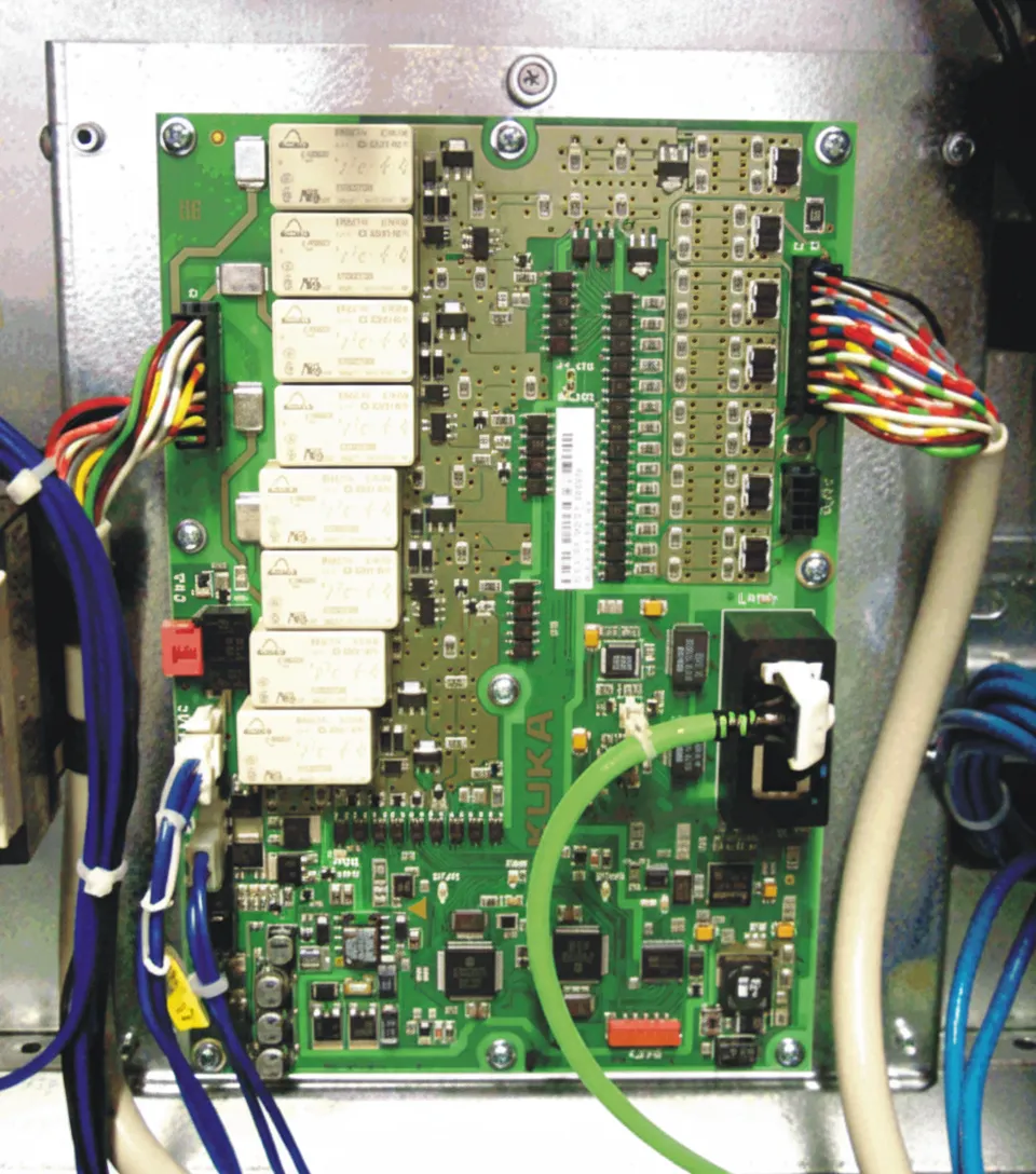
KUKA Robot X11 Field Wiring and Interface PCB Design Considerations
Field wiring interfaces, such as the X11 connector commonly used in KUKA systems, handle critical safety signals, emergency stops, enabling switches, and external device integration. These connections link the robot controller to perimeter guarding, safety PLCs, and operator stations.

PCB design best practices for such interfaces include:
- Robust connector footprints with reinforced mechanical mounting and controlled impedance for high-reliability signals.
- Isolation barriers between safety circuits and standard I/O to meet functional safety standards (e.g., ISO 13849 or IEC 61508).
- ESD protection, filtering, and surge suppression components placed close to connectors.
- Redundant ground paths and shielded cable support to minimize electromagnetic interference in factory environments.
- Test points and diagnostic LEDs integrated into the PCB for faster commissioning and troubleshooting.
Proper via design, trace spacing, and layer assignment in these interface boards significantly improve system uptime and safety compliance.

Major PCB Engineering Challenges in Robotics Applications
- Signal Integrity in Dynamic Environments: Continuous motion causes flexing and vibration. Rigid-flex and flex PCBs, combined with back-drilled vias and low-loss materials, help maintain signal quality for encoder and bus communications.
- Thermal Management: Motor drives and processors generate concentrated heat. Thermal via arrays, heavy copper planes, and metal-core options in high-power sections prevent thermal throttling and extend component life.
- EMI/EMC Compliance: High-current switching from servo drives creates strong electromagnetic fields. Strategic grounding, layer stacking, and shielding techniques are essential to avoid interfering with sensitive sensors and external equipment.
- Reliability Under Mechanical Stress: Vibration and shock demand strong solder mask, underfill strategies, and materials with matched CTE to prevent cracks and intermittent failures.
- Miniaturization and Modularity: Collaborative robots and space-constrained installations benefit from HDI technology, microvias, and modular daughterboard architectures for easier maintenance.
Manufacturing and Design Best Practices for Robot PCBs
Successful robotic PCB production requires close attention to:
- DFM for Robotics: Connector placement for cable strain relief, testability features, and mechanical reinforcement.
- Material Selection: High-Tg, low-CTE laminates, and halogen-free options for long-term reliability in industrial settings.
- Controlled Processes: Tight impedance tolerance, registration accuracy, and surface finishes (ENIG, hard gold) suitable for high-cycle connectors.
- Testing and Validation: In-circuit testing, boundary scan, and environmental stress screening to ensure boards perform under real-world robotic conditions.
These practices support scalability from prototype single units to high-volume production for global robotics manufacturers.
Partnering with Aivon for Advanced Robotics PCBs
From main controllers and servo drive boards to sensor interfaces and safety I/O modules, the quality of the PCB directly determines a robot’s precision, speed, safety, and service life.
Aivon offers comprehensive support — including stack-up optimization, signal/power integrity analysis, DFM reviews, and volume manufacturing — to help robotics companies build more capable and reliable systems.
Contact the Aivon team today to discuss your industrial or collaborative robot PCB requirements. Whether developing next-generation controllers, high-performance servo electronics, or integrated safety interfaces, we deliver the manufacturing excellence needed for demanding robotic applications.