 00:40
00:40
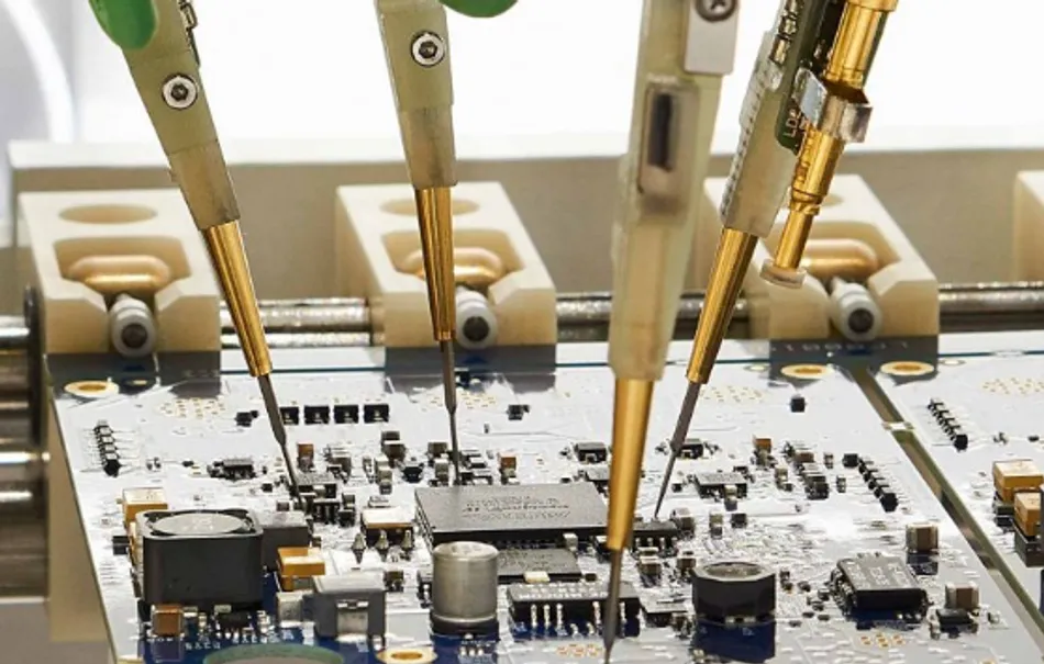
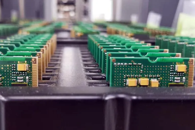
PCB Prototype
PCB prototypes serve as the foundational step in electronics development, allowing engineers, designers, and hobbyists to test and refine circuit designs before full-scale production. A PCB prototype is essentially a preliminary version of a printed circuit board, fabricated to validate functionality, identify design flaws, and ensure compatibility with components. For those searching for PCB Prototype resources, this tag aggregates essential information on rapid prototyping techniques, from initial schematic capture to assembly and debugging. Understanding these processes can significantly reduce time to market and minimize costly revisions in later stages. Key aspects covered here include selecting the right prototyping methods, such as single-sided or multilayer boards, and leveraging tools like CAD software for efficient layout. Practical applications range from consumer electronics to industrial automation, where prototypes help in iterating designs for optimal performance and reliability. Best practices emphasize thorough testing protocols, including electrical continuity checks, thermal analysis, and signal integrity verification, which are crucial for avoiding common pitfalls like short circuits or electromagnetic interference. By delving into the content under this tag, readers can gain actionable insights into cost-effective prototyping strategies, such as using online fabrication services for quick turnaround or DIY etching methods for small-scale projects. These resources also explore advancements in materials and manufacturing, like flexible PCBs for wearable tech, providing a comprehensive view that supports informed decision-making. Whether you are prototyping a simple sensor circuit or a complex embedded system, the articles here offer step-by-step guidance to enhance your workflow and achieve successful outcomes.
Video Guide
Technical Articles
Get in Touch
Send Message
- Products & Service
- Company
- About AIVON
- Contact
- News
- Blog
- Certification
-


- Payment
-


2026 AIVON.COM All Rights Reserved