 00:39
00:39
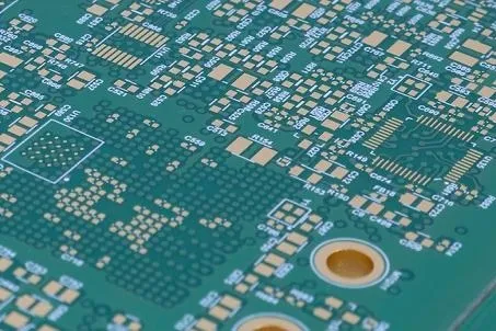
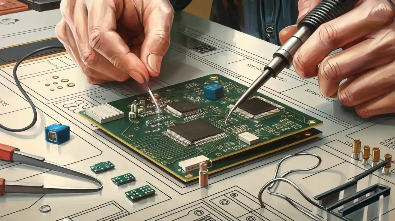
PCB Drilling
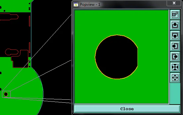
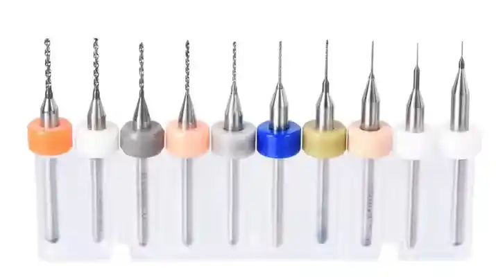
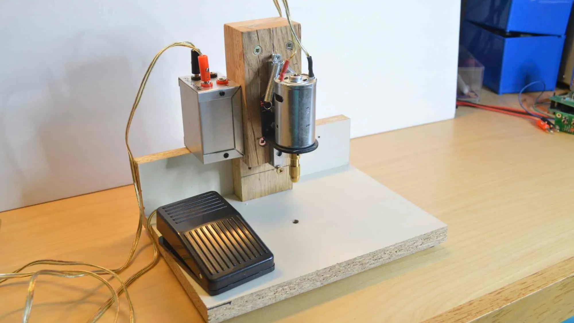
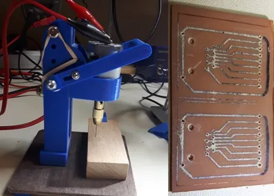
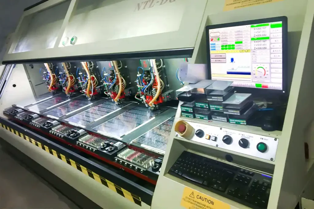
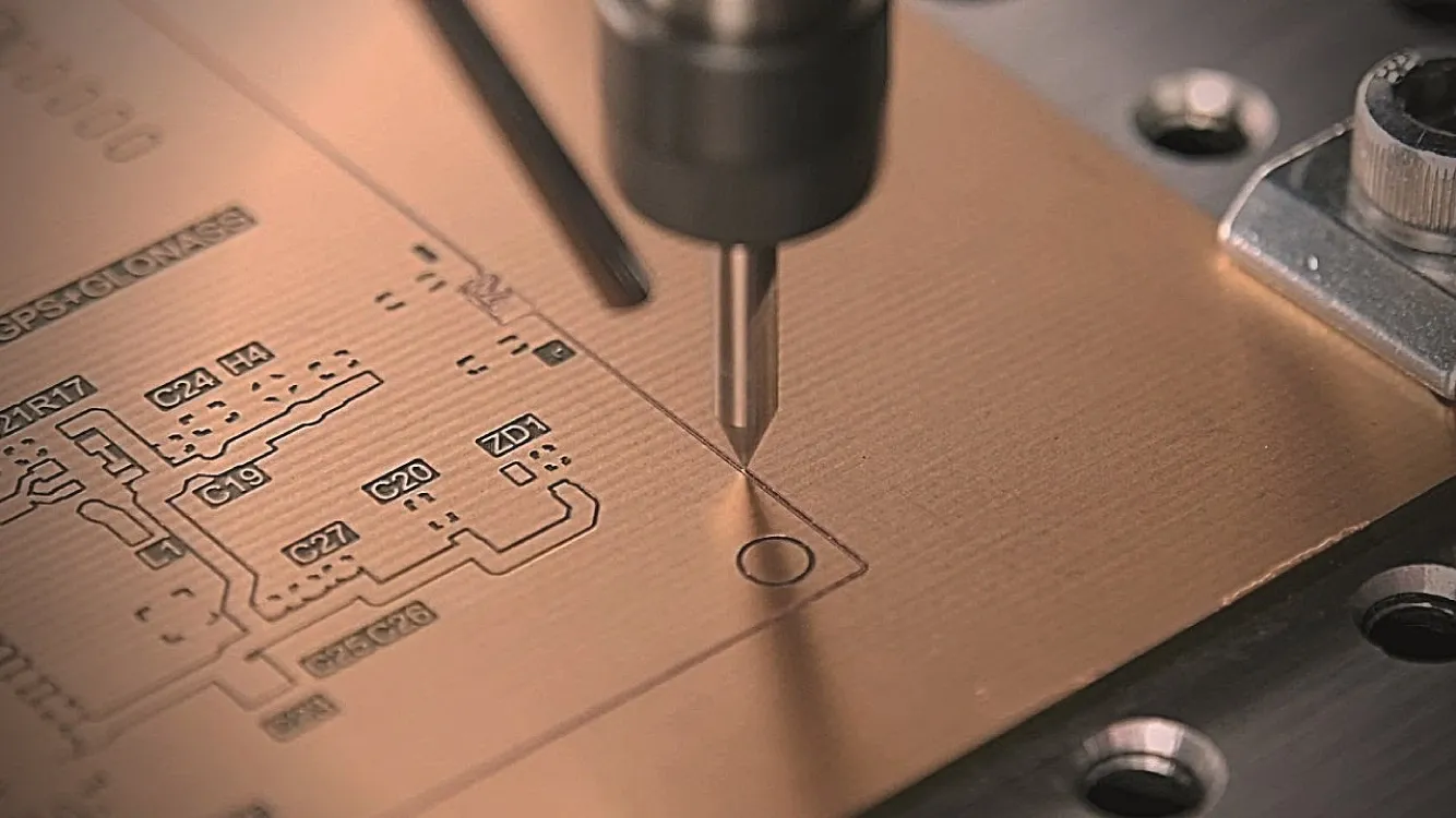
PCB drilling is a critical process in printed circuit board manufacturing, involving the precise creation of holes for component mounting, vias, and electrical connections. This tag encompasses a wide range of topics related to PCB drilling techniques, tools, and best practices, offering valuable guidance for engineers, hobbyists, and manufacturers seeking to optimize their designs and production workflows. Understanding PCB drilling begins with selecting the right drill bits, such as carbide or diamond-coated options, to handle various substrate materials like FR4 or flexible polymers. Key considerations include drill speed, feed rate, and spindle RPM, which directly impact hole accuracy and prevent issues like burrs or delamination. For instance, high-speed drilling can achieve tolerances as tight as 0.1mm, essential for high-density interconnect boards used in consumer electronics and automotive applications. Practical applications extend to both manual and automated processes. In prototyping, desktop CNC machines enable quick iterations, while industrial setups leverage laser drilling for microvias in advanced multilayer PCBs. Best practices emphasize proper stack-up design to minimize wander and ensure alignment, alongside regular maintenance to extend tool life and reduce downtime. Addressing common challenges, such as thermal management during drilling, helps avoid substrate damage and improves overall board reliability. Articles tagged under PCB drilling provide detailed insights into these areas, including step-by-step tutorials on software integration for drill file generation and case studies on troubleshooting real-world defects. By delving into these resources, readers can enhance their skills in achieving clean, precise holes that support robust circuit performance and efficient assembly.
Video Guide


Technical Articles
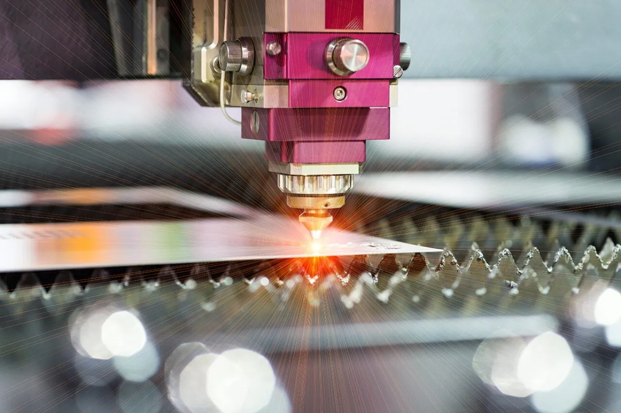
Optimizing Laser Drilling for Diverse PCB Materials: A Detailed Guide
HDI PCB Design: Overcoming Challenges in High-Density Interconnect
How to Avoid Countersink & Copper Issues in 3mm Thick FR4 PCB Manufacturing
DIY PCB Fabrication: Essential Tools and Techniques for the Home Lab
Simple Techniques for Accurate PCB Drilling at Home
Choosing the Right Drill Bit for Your DIY PCB Projects
DIY PCB Drilling: A Beginner's Guide to Mechanical Methods
Drill Hole Considerations for PCB DFM: Avoiding Common Manufacturing Errors
0.15mm Hole & Countersink Depth Control in 4-Layer HDI PCB
Evaluating 1.2mm Thickness Control and Depth Drill Precision in 4-Layer FR4 Production
Engineering Case Study: 4-Layer FR-4 PCB Hole Spacing Optimization and Silkscreen Character Height DFM Review
Engineering Case Study: 4-Layer 0.8mm Thin FR-4 PCB Counterbore Depth DFM Review
Engineering Case Study: Countersink Hole Risks on Thin 4-Layer 0.8mm FR4 PCB
Hole Design Guidelines for CNC Machining
CNC Machining Process Explained: From CAD File to Finished Part
PCB Drilling Equipment Maintenance: Tips and Best Practices for Longevity
PCB Manufacturing Process: A Step by Step Guide
Why is PCB Drilling Essential To Making Your Planned PCB Layout Work?
A Comprehensive Guide to PCB Drill Files: Understanding Gerber, Excellon, and More
DIY Controlled Depth Drilling: Build Your Own PCB Signal Booster
Get in Touch
Send Message
- Products & Service
- Company
- About AIVON
- Contact
- News
- Blog
- Certification
-


- Payment
-


2026 AIVON.COM All Rights Reserved