CNC machining design mistakes rarely announce themselves in the CAD file. They show up later — in the quote, in the first article inspection, or when the part fails to assemble cleanly onto the PCB. The designer usually had a reason: tighter packaging, lower weight, or a cleaner look. The shop then pays for it in extra passes, fragile tools, or secondary operations that were never budgeted.
Five of these choices account for most of the avoidable cost on machined housings, brackets, and heat sinks that interface with PCBs. The rest are smaller but still add up across a production run.
Deep Cavity Designs That Force Long Tools and Multiple Setups
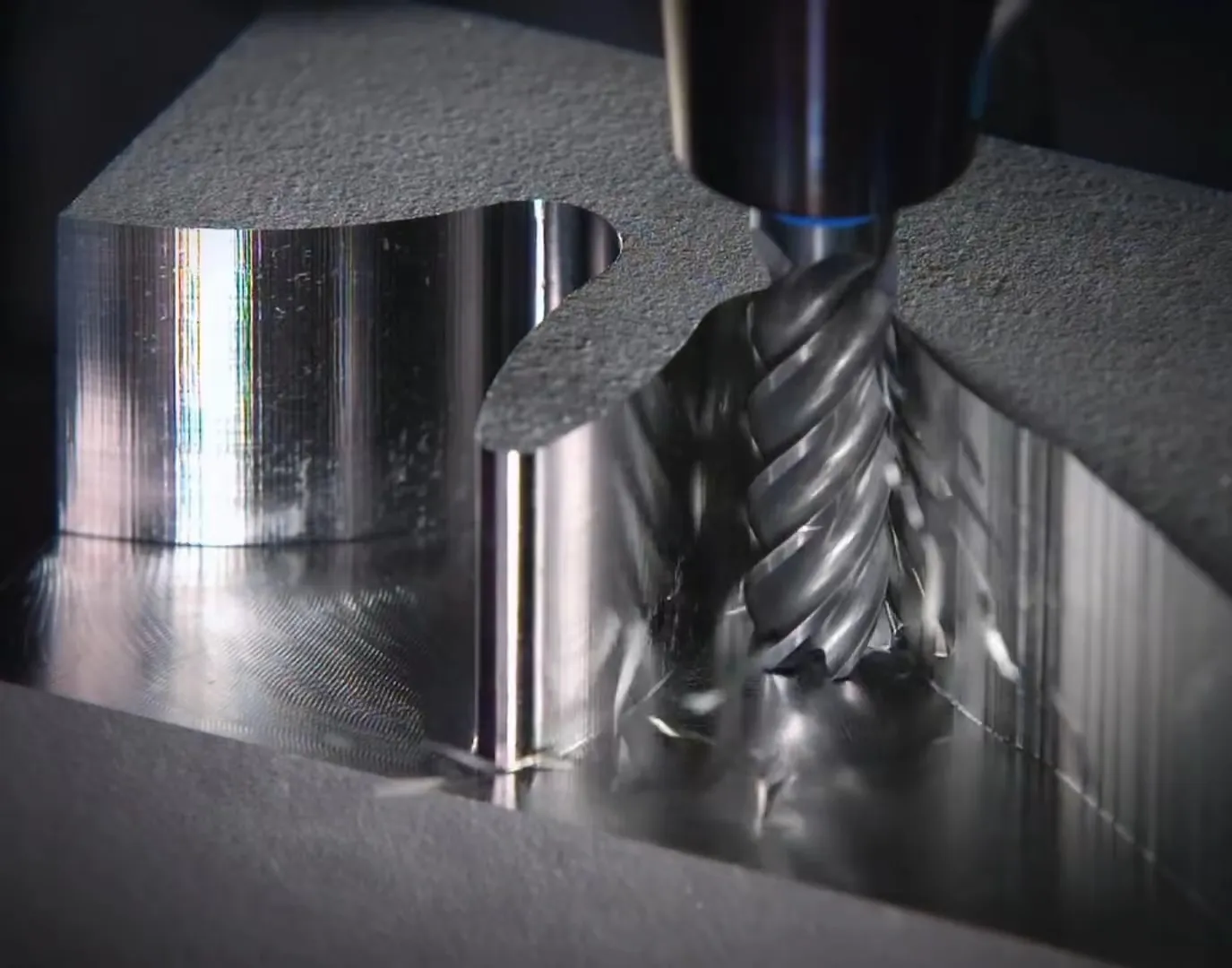
A pocket that drops more than three times the tool diameter below the top surface immediately changes the machining strategy. The end mill must be longer, its stiffness drops, and the programmer has to reduce feed and speed to control chatter. Roughing then happens in many shallow steps so the tool does not deflect or pack chips at the bottom. In aluminum that already machines easily, a 15 mm deep pocket can easily triple the cycle time compared with an 8 mm version of the same opening.
Chip evacuation becomes unreliable once the pocket is narrow and deep. Recutting chips damages the floor finish and shortens tool life. Shops either slow the whole job or add pecking cycles that further extend runtime. When the cavity is meant to clear PCB components or a connector stack, the designer often draws it to the exact envelope needed. That exact envelope is exactly what creates the problem on the mill.
The practical limit most shops accept without extra cost is roughly 2.5–3× the largest roughing tool diameter. Beyond that, either open the pocket width to allow a shorter stubby tool or step the cavity in tiers so each level stays within reach. Adding a through-hole or relief at the bottom for chip exit sometimes helps more than any parameter change.
Thin Wall Sections That Deflect Under Cutting Forces
Thin walls look elegant in the model and save weight on handheld or portable electronics. On the machine they act like a spring. Side cutting forces from the end mill push the wall sideways; if the thickness-to-height ratio is too low the wall vibrates, leaves a wavy surface, and drifts out of tolerance. The programmer then has to drop feed rates dramatically or add temporary support stock that must be removed in a second operation.
For 6061 aluminum, walls taller than 10–12 mm usually need at least 1.0–1.2 mm thickness before chatter becomes hard to manage on a standard 3-axis mill. Below that, even moderate stepovers can cause the wall to deflect 0.1 mm or more. When the wall also carries mounting holes that must line up with a PCB, the dimensional error shows up at final assembly. The part may still pass a CMM check on the bench but fails when screwed down.

A small fillet at the base where the wall meets the floor adds stiffness without much extra material. If the design truly needs the thin section, the shop may machine it from thicker stock and leave a web, or use 5-axis to approach from the side and reduce the moment arm. Both options cost more than designing the wall thicker from the start.
Sharp Internal Corners That Cannot Be Produced With Standard Tooling
A true zero-radius internal corner is geometrically impossible with any rotating end mill. The tool always leaves a radius equal to its own radius. When the drawing shows a sharp corner, the shop must either leave the radius (and risk interference with a mating PCB edge or connector) or move to EDM, broaching, or hand work. All three add cost and lead time.
Designers often carry over the sharp-corner habit from sheet-metal or injection-molded parts. In those processes sharp is free. In CNC it is not. The mismatch appears most often at the corners of pockets meant to receive PCB modules or at the base of bosses that locate connectors. The part looks correct on screen; it does not fit during first-article build.

Specifying a minimum internal radius of 0.5 mm or 1.0 mm (matching common end-mill sizes) removes the issue in most cases. If a truly sharp corner is functionally required, a small relief groove or a separate pressed-in insert usually costs less than forcing the mill to approximate zero radius.
Overly Tight Tolerances Applied to Non-Critical Features
A general tolerance of ±0.05 mm is realistic for most milled features on aluminum or mild steel with standard setup. Pushing non-critical dimensions to ±0.01 mm or tighter forces slower feeds, finer stepovers, more frequent tool compensation, and extra CMM time. Thermal drift, tool wear, and slight fixture movement that were previously acceptable now produce scrap.
The habit often comes from copying tolerances from a previous similar part or from a simulation that assumed perfect geometry. When the tight tolerance lands on a mounting hole pattern that must align with a PCB, it may be justified. When it lands on the outer profile of a cosmetic cover, it is usually unnecessary cost. Shops see the difference immediately in the quote.
Apply tight tolerances only where fit, sealing, or electrical contact actually demands them. Use a general tolerance block referencing ISO 2768-m or a company standard for everything else. That single change frequently reduces machining time and inspection cost by 20–30 % with no loss in function.
Unreasonable Structures That Require Extra Setups or Custom Fixturing
Features on five or six sides, undercuts with no clear tool entry, or intersecting thin sections that leave the part unstable on the table all force additional setups. Each flip adds probing time, datum shift risk, and potential for misalignment that later shows up when the part is screwed to the PCB. Some geometries simply will not sit flat without custom soft jaws or a dedicated fixture plate. Those fixtures are rarely free.
Designers create these structures when they optimize purely for function or for the smallest possible envelope. The machining sequence is an afterthought. In practice, parts that can be completed in one or two setups almost always quote lower and arrive with better dimensional consistency.
Add temporary stock bosses or tabs that the shop can grip, then remove in the last operation. Keep critical datums on one or two faces. Avoid undercuts unless they can be reached with a standard keyseat cutter or by tilting the part on a 5-axis machine. When the geometry truly needs complexity, consider splitting the part into two simpler pieces that assemble later; the total cost is often lower.
Other Recurring CNC Machining Design Mistakes That Add Cost
Several smaller but frequent choices also inflate quotes:
- Specifying high surface finishes (Ra 0.4 or better) on faces that will be hidden or gasketed — most structural surfaces only need Ra 1.6 or 3.2.
- Placing small holes or thin walls too close to the part edge so the material breaks out or deflects during drilling.
- Using non-standard thread sizes or depths in blind holes without relief grooves, forcing special taps or EDM.
- Designing large material removal volumes without leaving enough stock for stress relief; the part warps after roughing and needs extra straightening or semi-finishing passes.
- Ignoring that very small features require tiny tools that run at low feed rates and break easily, multiplying cycle time.
Each item by itself may seem minor. Together they turn a straightforward 3-axis job into something that needs 5-axis time, custom tooling, or hand finishing.
Engineering Lessons From These CNC Machining Design Mistakes
The common thread is simple: decisions made in the CAD model without reference to how material is actually removed. Tool stiffness, chip flow, setup stability, and achievable tolerance all have physical limits. When a design pushes against those limits, cost rises faster than linear.
Most of these issues are caught early if the mechanical designer reviews the model with someone who has run the machines or who regularly performs DFM checks for parts that will later carry or enclose a PCB. Changing a corner radius from zero to 0.8 mm, opening a pocket by 2 mm, or relaxing a non-critical tolerance rarely affects function but frequently cuts the quote by a noticeable margin. The parts that reach the shop floor with the fewest of these embedded mistakes are the ones that arrive on time and at the expected cost.