In our CNC shop, every production run starts with a strict file review that follows proven CNC machining design guidelines. We require a complete STEP or STP 3D model paired with a fully dimensioned 2D technical drawing before the CAM team generates toolpaths. This combination is the standard process that prevents most manufacturing issues from reaching the shop floor.
How CAM teams apply CNC machining design guidelines during file validation
The CAM programmer loads the STEP file first and runs geometry checks for watertight solids, missing faces, and import errors. Every feature is then cross-referenced against the 2D drawing for tolerances, datums, material callouts, and surface finish requirements. Following these CNC machining design guidelines at intake eliminates assumptions that would otherwise appear during setup or inspection. Thread notes must specify size, pitch, and tolerance class. Hole patterns need position tolerances tied to clear datums. Without this data, quoting pauses until clarification arrives.

Why incomplete 3D models create problems in real production
Design software focuses on nominal geometry while production must control material behavior, tool deflection, and thermal effects. A STEP file alone does not declare which dimensions are critical or what alloy temper is required. Our standard CNC processes hold ±0.05 mm on general features; tighter tolerances or special materials must be stated explicitly. This gap is the most frequent reason for back-and-forth during DFM review.
Real production consequences when CNC machining design guidelines are ignored
Vague tolerances lead to conservative quoting and extra inspection time. Wrong material assumptions have caused full batch scrap and urgent re-orders that delay the entire schedule. Thin walls or deep narrow pockets not flagged early produce chatter, deflection, or tool breakage. Multi-setup parts accumulate datum error that only becomes visible at final inspection, resulting in rejected parts and rework costs that could have been avoided by following standard CNC machining design guidelines upfront.
How factories implement stock allowances and toolpath strategies
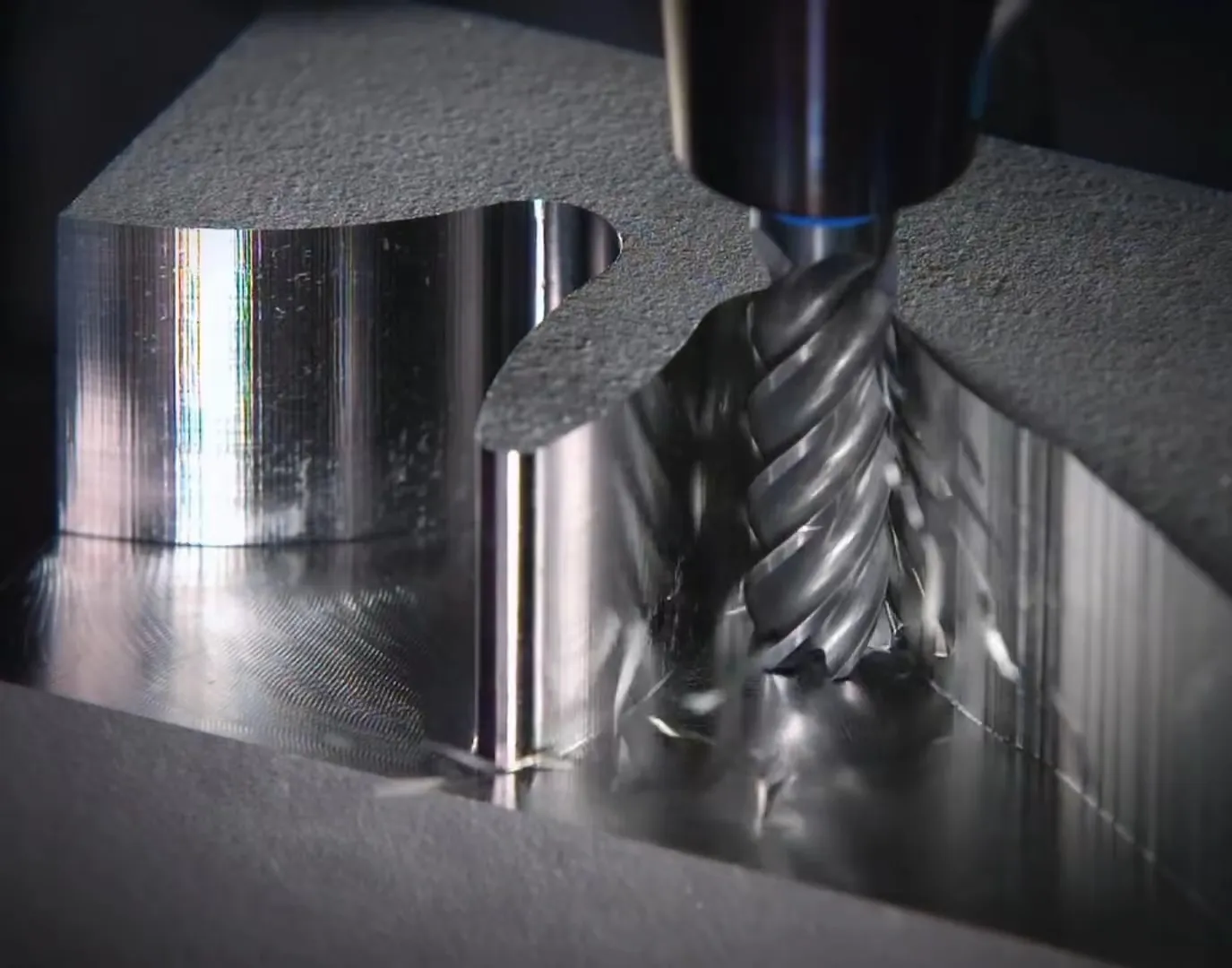
We apply consistent rules based on material. Aluminum parts receive 0.3–0.5 mm stock allowance on machined faces. Internal corners are programmed with radii matching or exceeding the selected end mill radius plus clearance. Wall thickness below 1.5 mm in metal triggers custom fixturing review. Features requiring tools smaller than 3 mm diameter or length-to-diameter ratios over 4:1 are noted for increased cycle time and risk. Surface finish callouts (Ra 3.2, 1.6, or 0.8 µm) determine the number of finishing passes and feeds. These are the practical CNC machining design guidelines that keep jobs predictable on the floor.

Material and surface treatment specifications that keep quoting accurate
We stock common grades such as 6061-T6 aluminum, 304 stainless, and POM. Any other alloy or temper adds procurement time that must be included in the quote. Surface treatment notes must be precise: MIL-A-8625 Type II Class 2 black anodize, passivation per ASTM A967, or powder coat to a specific RAL code with masking zones clearly marked. Vague descriptions like "anodized" force clarification and extend lead times.
Preparation checklist before submitting files for quote
Provide the STEP file, complete 2D drawing with tolerances and GD&T where applicable, exact material grade, surface treatment details, target quantity, and expected delivery date. Quantity matters because low-volume prototypes use different workholding than repeat production orders. Mating part information helps align datums and avoid tolerance stack-up issues. Complete packages move from upload to first-article approval faster and with fewer surprises.

When lighter documentation is acceptable for prototypes
For single urgent prototypes where the designer is available for quick confirmation we occasionally accept a detailed 3D PDF with embedded notes. Even then we record every assumption on tolerances and material and require customer sign-off before machining begins. All production quantities and regulated parts require the full package per our CNC machining design guidelines. The exception exists only to support fast-turn development work without compromising overall process reliability.
Applying these CNC machining design guidelines from the production perspective ensures accurate quoting, smooth CAM programming, and high first-pass yield. Complete data packages reduce cost and lead time while protecting part quality on every job.