Digital multimeters (DMMs) are fundamental tools in PCB design validation, prototyping, production testing, and failure analysis. From verifying power rails and signal continuity to detecting manufacturing defects, a well-chosen DMM provides the accuracy and versatility required for modern multilayer PCB quality control. At Aivon, we integrate precise multimeter measurements throughout our manufacturing process to ensure excellent electrical performance, reliability, and compliance in high-speed, RF, and industrial boards.
Analog vs Digital Multimeters: Why Digital Dominates PCB Work
Analog multimeters offer simple needle-based displays but suffer from parallax errors, lower resolution, and limited input impedance. Digital multimeters provide clear LCD/LED readouts, high accuracy (typically 0.5% or better), auto-ranging, and features such as true RMS measurement and capacitance testing.
For PCB applications, digital multimeters are superior because:
- High Input Impedance: Minimizes circuit loading when measuring sensitive analog or high-impedance nodes.
- Precise Readings: Essential for verifying voltage tolerances on power distribution networks (PDN) and reference voltages.
- Additional Functions: Continuity with audible beep, diode testing, capacitance, frequency, and temperature measurements streamline PCB validation workflows.
While analog meters still appear in basic continuity checks, digital models deliver the resolution and data logging capabilities demanded by complex HDI and multilayer PCB manufacturing.
Core Functions of Digital Multimeters for PCB Testing
Modern DMMs support multiple measurement modes critical to PCB engineering:
- DC/AC Voltage: Verifying power rail stability, signal levels, and bias voltages. Critical for confirming proper operation of 3.3V, 1.8V, and 1.0V rails in digital designs.
- Current Measurement: Assessing power consumption and detecting excessive leakage in assembled boards.
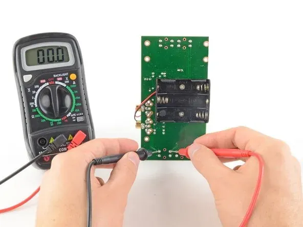
- Resistance and Continuity: Validating trace integrity, via connections, and solder joint quality.
- Capacitance and Diode Testing: Checking decoupling capacitors and protection diodes on the board.
- Frequency and Duty Cycle: Supporting basic clock signal verification.
These functions help bridge schematic intent with actual fabricated performance during Aivon's quality assurance stages.
Best Practices and Quick Rules for Safe, Accurate PCB Measurements
Effective multimeter usage on PCBs requires disciplined techniques:
- Always start with the highest range and move downward (or use auto-ranging) to protect the instrument and board.
- Use sharp, high-quality probes with minimal tip resistance for fine-pitch test points and vias.
- Maintain proper polarity when measuring DC voltages to avoid reverse bias issues on components.
- Discharge capacitors before resistance or continuity testing to prevent false readings or instrument damage.
- Use the "relative" or "zero" function to null out test lead resistance during low-ohm measurements on traces and planes.
Common Mnemonics used by Aivon engineers:
- "Red to Power, Black to Ground" for voltage checks.
- "Continuity Check Before Power-On" to prevent short-related damage.
Following these rules reduces measurement errors and protects sensitive high-density PCBs during validation.
Detecting Shorts, Opens, and Leakage on PCBs
One of the most valuable applications of digital multimeters in manufacturing is fault isolation:
- Shorts Detection: Use resistance or continuity mode to scan between power and ground planes, adjacent traces, or vias. Low resistance readings (< 1 ohm) often indicate solder bridges, debris, or laminate defects.
- Opens Identification: Check continuity along high-speed traces, power distribution paths, and ground returns. High resistance indicates broken traces, poor via plating, or cracked solder joints.
- Leakage Current Measurement: Measure resistance between isolated nets or from power rails to chassis ground. Unexpected low resistance reveals insulation breakdown or contamination that can cause field failures.
These measurements are especially important after lamination, drilling, plating, and assembly to catch process-related defects before boards proceed to functional testing.
Common Multimeter Issues and Troubleshooting in PCB Contexts
Engineers frequently encounter these challenges when testing PCBs:
- Incorrect Readings: Often caused by poor probe contact, oxidized test points, or residual flux. Clean surfaces and use appropriate pressure.
- Overload or Blown Fuse: Results from measuring voltage while in current mode or probing live high-energy circuits. Always verify dial position before connecting.
- Fluctuating Values: Usually indicates unstable probe contact or active switching on the board. Use hold functions or min/max recording.
- Battery or Calibration Drift: Regular calibration ensures accuracy for tight-tolerance measurements required in RF and high-speed digital designs.
For voltage measurements between test points (such as transformer windings or power domains), always consider both DC and AC components, especially in mixed-signal or power electronics PCBs.
PCB Manufacturing Applications and Aivon Recommendations
In a professional PCB production environment, digital multimeters support:
- Bare board electrical testing (netlist verification)
- Post-assembly power-up sequencing checks
- Thermal stress and reliability testing validation
- Failure analysis during root cause investigation
When selecting a DMM for PCB work, prioritize models with high resolution (4.5-6.5 digits), true RMS capability, and robust input protection. Combine multimeter testing with automated flying probe or in-circuit test systems for comprehensive coverage.
At Aivon, rigorous multimeter-based verification forms a core part of our quality management system. This meticulous approach, combined with advanced signal integrity tools, ensures every board we manufacture meets stringent performance and reliability standards for telecommunications, automotive, industrial control, and high-frequency applications.
Mastering digital multimeter techniques is essential for any team committed to high-reliability PCB design and manufacturing. From basic continuity checks to detailed leakage analysis, these instruments provide the foundational data that supports superior stack-up decisions, material selection, and process control.