Medical infrared thermometers have become essential tools for non-contact temperature measurement in clinical and consumer settings. At the heart of every accurate, reliable device lies a carefully engineered printed circuit board (PCB) that integrates infrared sensors, signal-conditioning circuitry, microcontrollers, power management components, and often wireless or RFID modules. PCB layout, material selection, grounding strategies, and manufacturing processes directly determine measurement precision, battery life, thermal stability, and long-term reliability under varying environmental conditions.
For PCB manufacturers and design engineers, infrared thermometry introduces stringent requirements for low-noise analog paths, thermal isolation, electromagnetic compatibility (EMC), and ultra-low power operation. Meeting these challenges at the board level enables compact, regulatory-compliant devices that deliver consistent performance in demanding medical applications.
Infrared Thermometry Principles and PCB-Level Signal Processing
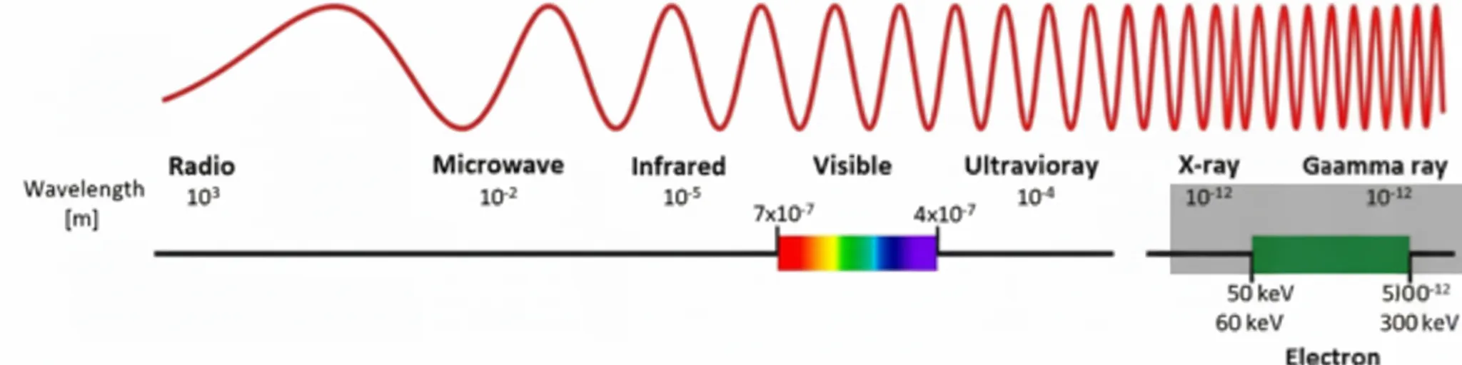
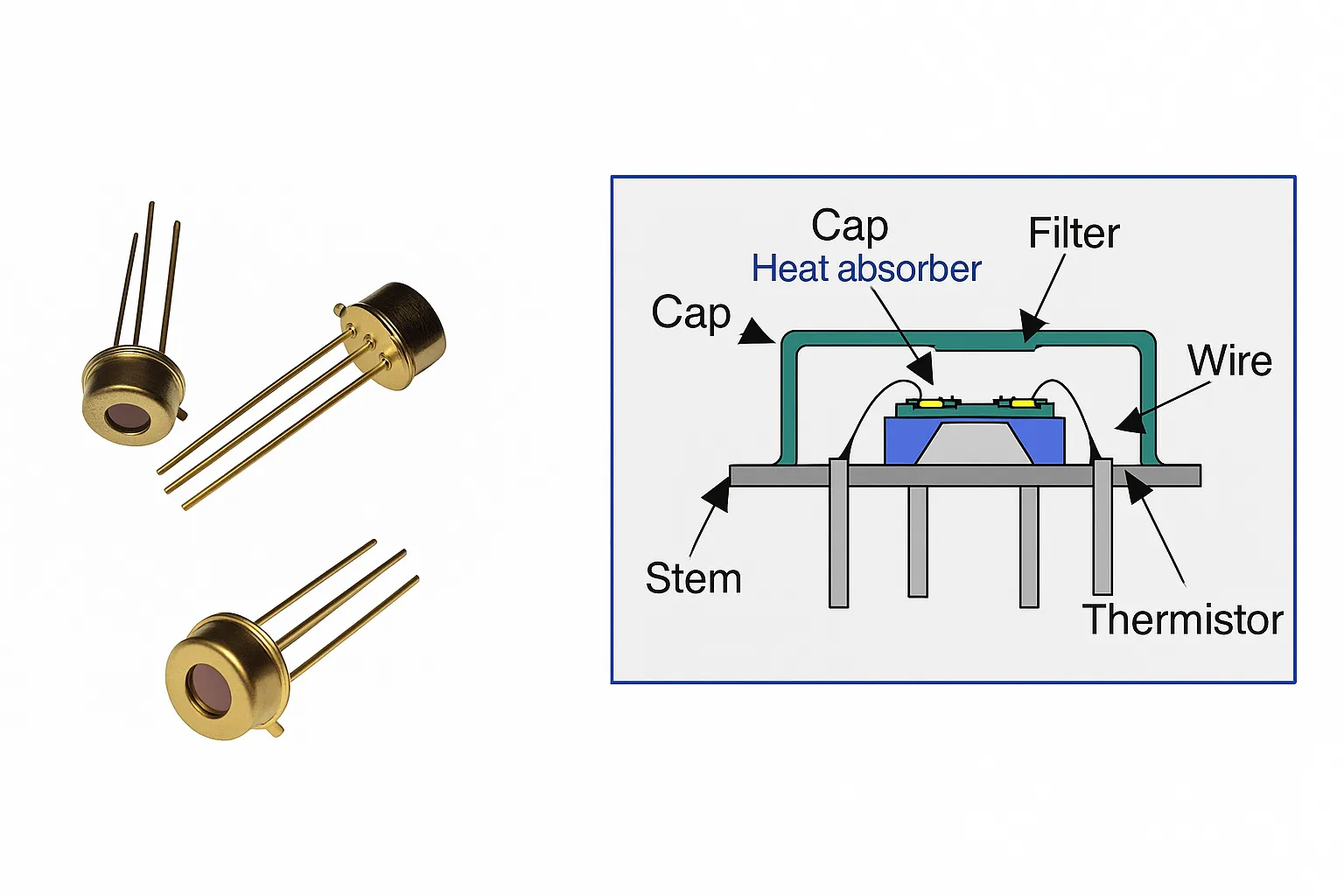
Infrared thermometers measure surface temperature by detecting thermal radiation emitted from the target. A thermopile or pyroelectric sensor converts incident infrared energy into a small voltage or current signal. This weak analog output must be amplified, filtered, and digitized with minimal noise and offset.
On the medical PCB, designers route sensitive analog traces away from digital clocks and switching regulators using star grounding or dedicated ground planes. Controlled-impedance routing and proper decoupling capacitors preserve signal integrity. Shielding techniques, such as ground pours or metal cans over the sensor area, reduce electromagnetic interference that can degrade measurement accuracy. High-Tg laminates and low-loss dielectric materials help maintain stable performance across temperature swings encountered in handheld or clinical environments.
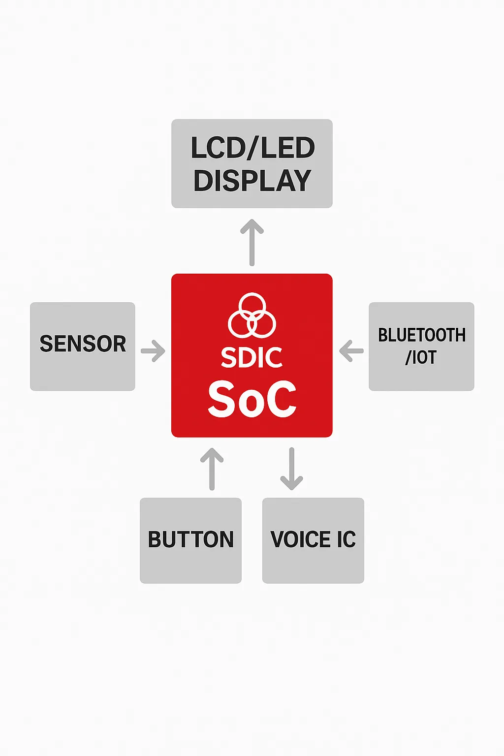
Single-Chip Solutions and Compact PCB Integration
Modern single-chip infrared thermometer solutions combine the infrared sensor, amplifier, ADC, and microcontroller interface into one package, dramatically reducing board space and external component count. These integrated devices simplify layout while improving reliability by minimizing solder joints and interconnect parasitics.
PCB engineers must still address critical placement considerations: the sensor window requires a clear optical path with minimal obstruction from nearby components. Thermal vias and copper pours help dissipate any self-heating from the chip, while careful decoupling and separate analog/digital power domains prevent noise coupling. HDI techniques or multilayer stack-ups allow dense integration of supporting circuitry without increasing overall device thickness.
Design Factors for Infrared Thermometer Accuracy
Measurement accuracy depends on optical design, ambient temperature compensation, and electronic stability. Emissivity settings, distance-to-spot ratio, and ambient drift compensation are implemented through firmware, but the underlying PCB layout determines how cleanly these corrections can be applied.
Key PCB factors include:
- Low-offset, low-drift amplifiers with proper guard traces
- High-resolution ADCs placed close to the sensor to shorten analog signal paths
- Temperature sensors (often NTC thermistors) positioned to accurately track ambient conditions without being influenced by board self-heating
- Isolation between the optical sensor area and heat-generating components such as LEDs or wireless modules
Proper copper thickness and thermal relief patterns further ensure that localized heating does not introduce measurement errors.
Power Design Options for Battery-Powered Infrared Thermometers
Battery life is critical for portable medical devices. Designers choose between linear regulators, switching converters, or hybrid approaches depending on required voltage rails and efficiency targets. Low-quiescent-current components and intelligent power sequencing extend runtime while maintaining measurement readiness.
On the PCB, efficient power distribution networks with short, wide traces minimize voltage drops. Strategic placement of decoupling capacitors near power pins and separation of noisy digital supplies from clean analog rails are essential. Advanced power-management ICs with integrated fuel gauges or dynamic voltage scaling can be incorporated, requiring careful layout of sense resistors and feedback loops. Conformal coatings and moisture barriers protect against humidity-related leakage currents that can drain batteries prematurely.
NTC Thermistors, RFID Integration, and Advanced Sensor Fusion
NTC thermistors provide precise ambient temperature compensation for infrared measurements. Accurate placement on the PCB—away from heat sources yet thermally coupled to the environment—is vital. Short, shielded traces to the ADC input reduce noise pickup.
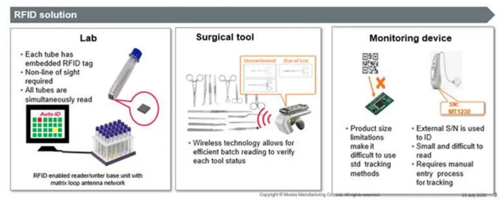
RFID or NFC modules enable device identification, calibration data storage, or wireless data transfer in medical workflows. PCB antenna design, impedance matching, and isolation from sensitive analog sections are critical to maintain both communication range and measurement integrity. Multilayer boards with dedicated RF layers or ground shielding help achieve reliable performance without compromising the low-noise requirements of the thermopile channel.
Manufacturing, Reliability, and Regulatory Compliance in Medical-Grade Infrared Thermometer PCBs
Medical-grade infrared thermometers demand high-reliability PCBs manufactured under controlled processes. Precise etching, advanced lamination, and surface finishes such as ENIG ensure long-term contact integrity. Rigorous in-circuit testing and boundary-scan techniques verify analog signal paths. Design-for-manufacturability (DFM) reviews early in the layout phase help avoid issues such as insufficient thermal relief, via-in-pad problems, or electromagnetic coupling that could affect accuracy or compliance with IEC 60601 standards.
Failure analysis often reveals root causes such as thermal gradients across the board, ground bounce, or moisture ingress—problems mitigated through proper stack-up design, conformal coating, and robust mechanical-PCB co-design.
Conclusion
Successful medical infrared thermometers ultimately depend on the quality and sophistication of their underlying PCBs. By prioritizing optimized analog layouts, robust grounding and shielding, precise thermal management, efficient power distribution, and rigorous manufacturing processes, PCB engineers enable higher measurement accuracy, extended battery life, and superior long-term reliability. As demand grows for smarter, more connected, and miniaturized diagnostic tools, collaboration between device developers and specialized medical PCB manufacturers remains essential for delivering clinically reliable infrared thermometry solutions that meet both regulatory requirements and real-world performance expectations.