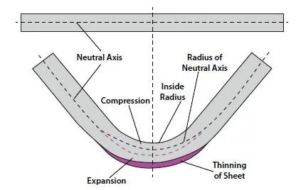
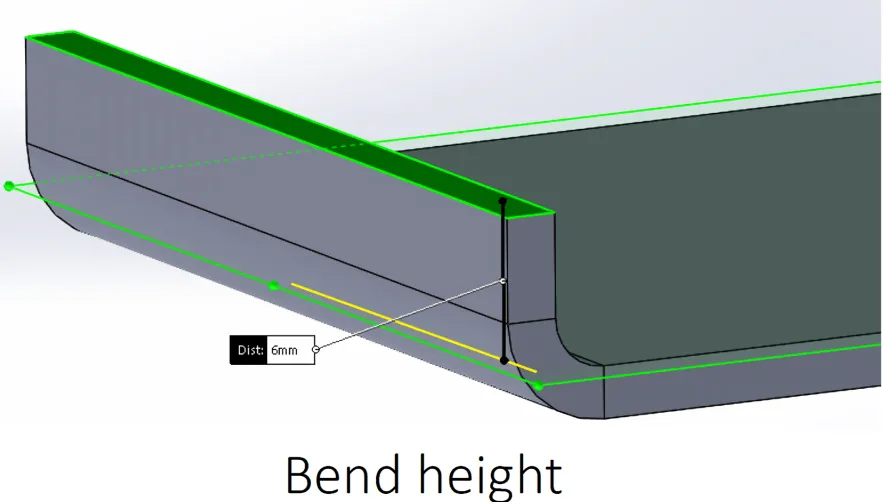
In production we see the same sheet metal design mistakes repeated across jobs. Most issues involve bend direction conflicts, insufficient hole-to-edge distances, unrealistic tolerances, and poor material selection. Our CAM team flags these during DFM review and suggests corrections before cutting blanks to avoid rework or scrap.
Why Bend Direction Creates Forming Problems in Production
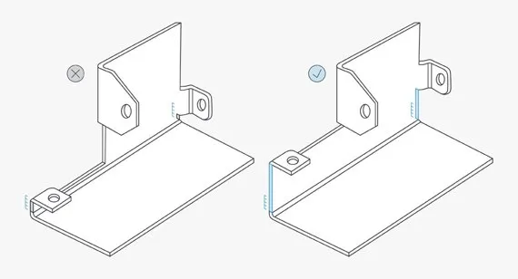
Bend direction must consider grain direction of the sheet and part geometry. When bends are specified against the grain or in conflicting orientations on the same part, cracking appears along the bend line. We usually request the drawing to indicate bend line direction or default to the most practical forming sequence.
In the press brake, operators adjust the program to minimize flips but conflicting requirements force extra setups or hand corrections that increase cost and risk distortion.
Hole Edge Distance Issues That Cause Tearing and Distortion
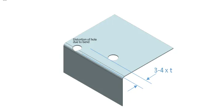
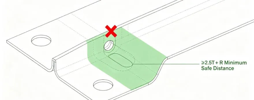
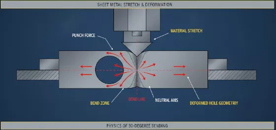
Holes placed too close to bend edges or to each other lead to material tearing during forming. Standard rule in our shop is at least 1.5 times material thickness from bend tangent line to hole edge. When this is ignored the hole distorts into an oval shape or the edge cracks, especially on thinner sheets.
During punching and bending these areas experience high stress. Parts with this mistake require manual trimming or complete scrap after forming.
How Unrealistic Tolerances Affect Sheet Metal Fabrication
Calling out ±0.05mm on formed features or hole positions across bends is difficult to hold consistently. Sheet metal springback and material variation make tight tolerances expensive. We apply standard tolerances of ±0.1mm to ±0.3mm depending on thickness and feature type unless critical areas are clearly identified and dimensioned from specific datums.
Overly tight tolerances trigger secondary operations like reaming or manual adjustment, driving up labor time and reject rates. We flag these during DFM and propose relaxed values where function allows.
Material Selection Errors That Impact Manufacturability
Choosing stainless for parts that need complex forming or selecting thick material for small enclosures creates forming challenges. Some alloys have poor bendability and require larger bend radii. We see mismatches when designers pick material based only on strength or corrosion needs without considering fabrication behavior.
Wrong material thickness also causes issues — too thin leads to warping, too thick increases tonnage requirements and tooling wear. Production prefers common gauges like 1.0mm, 1.5mm, or 2.0mm for aluminum and steel because tooling and experience are optimized for them.
What Happens When Sheet Metal Design Mistakes Reach the Floor
Bends crack, holes distort, parts do not assemble correctly, and flat patterns fail to unfold properly in software. These lead to high scrap rates, multiple iterations, and delayed deliveries. In worst cases the entire batch is rejected after powder coating or assembly when problems become visible.
How Factories Compensate for Common Sheet Metal Design Mistakes
During CAM processing we adjust bend allowances based on actual material and machine calibration. For problematic features we add relief notches or modify hole positions slightly while staying within functional limits. Our DFM feedback includes specific recommendations with drawings when needed.
We maintain a database of successful bend radii and material combinations that guides suggestions for future designs. Early involvement in the design phase prevents most issues before steel is cut.
Practical Rules We Recommend for Avoiding Sheet Metal Design Mistakes
Keep hole-to-edge and hole-to-bend distances generous. Standardize bend radii to one or two values per part. Call out critical tolerances only where required and reference proper datums. Match material and thickness to both function and fabrication capability. Provide clear bend direction and grain requirements when important.
These adjustments usually add very little to material cost but save significant time and money in production.
When Certain Sheet Metal Design Mistakes Can Be Accepted
Low volume prototypes sometimes accept tighter tolerances or marginal hole placements if the designer accepts higher risk of rework. Simple brackets with minimal forming can bypass some rules. We evaluate case by case and communicate the trade-offs clearly before starting.
Avoiding common sheet metal design mistakes early keeps parts moving smoothly from flat pattern to finished product with minimal surprises.